Method for measuring self-impedance and mutual impedance between underground grounding devices

A technology of a grounding device and a measurement method, which is applied in the direction of grounding resistance measurement, etc., can solve the problems of heavy calculation workload, difficult modeling, and unsatisfactory calculation results, and achieve the effect of accurate measurement results and easy operation.

Active Publication Date: 2012-07-18
CHINA ELECTRIC POWER RES INST +1
View PDF4 Cites 4 Cited by
  • Summary
  • Abstract
  • Description
  • Claims
  • Application Information

AI Technical Summary

Problems solved by technology

Although the calculation of the general underground current field can accurately calculate the coupling relationship between the grounding bodies, for systems with complex power networks on the ground, modeling is difficult, the calculation workload is large, and the calculation results are not ideal.

Method used


Image

  • Method for measuring self-impedance and mutual impedance between underground grounding devices
  • Method for measuring self-impedance and mutual impedance between underground grounding devices
  • Method for measuring self-impedance and mutual impedance between underground grounding devices

Examples


Embodiment

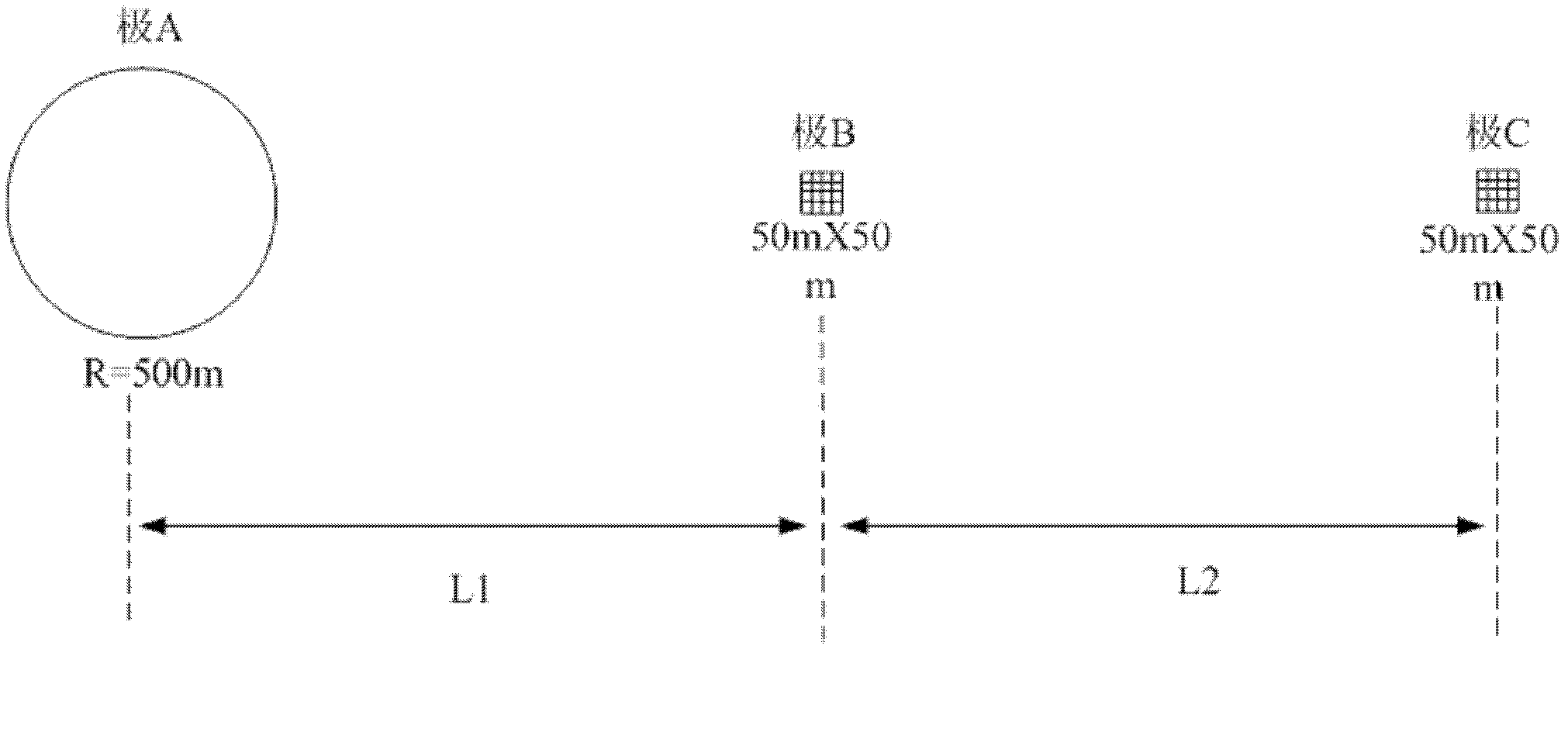
[0039] Example: such as image 3 As shown, the grounding devices A, B and C are the DC grounding pole A and the two substation grounding grids B and C respectively. First, using the port characteristics of the underground grounding system, the potential at each grounding device is written as the sum of the responses generated at the grounding device by the injection current of each node:

[0040] U 1 U 2 U 3 = k 11 k 12 k 13 ...


PUM


Abstract

The invention relates to a method for measuring self-impedance and mutual impedance between underground grounding devices, which comprises the steps of firstly, arranging an underground grounding system consisting of a plurality of grounding devices which comprise direct-current grounding electrodes and alternating-current grounding nets, and finding out a relation between self-admittance and response coefficients and mutual admittance and response coefficients according to port characteristics of the underground grounding system and analysis of an equivalent admittance circuit diagram; secondly, calculating out corresponding coefficient values by utilizing distribution of an underground current field, and then determining a self-admittance value and a mutual admittance value; and finally, obtaining self-impedance and mutual impedance between corresponding nodes according to a reciprocal relation of the impedance and the admittance, and establishing power networks between underground grounding systems. The method can achieve accuracy of measurement results of the self-admittance value and the mutual admittance value of each grounding device, can be applied to software modeling of a power system with complex ground power networks, and can be widely applied to the power system.

Description

technical field [0001] The invention relates to a method for measuring impedance in a power system, in particular to a method for measuring the self-impedance and mutual impedance of an underground grounding device used between a grounding electrode in a DC power transmission system and a grounding grid of a nearby AC substation. Background technique [0002] At present, power system simulation software such as BPA and EMTP can accurately and quickly calculate complex large-scale power networks on the ground by building circuit models, but they are powerless for underground resistive coupling calculations such as the potential rise of nearby grounding grids caused by DC grounding electrodes. For a large-scale power network with multiple grounding devices, other methods must be used to obtain the mutual impedance between each grounding device in order to accurately model and solve the entire power network. Although the general underground current field calculation can accurat...

Claims


Application Information

Patent Timeline
IPC IPC(8): G01R27/20
Inventor 郭剑白锋蒋俊
Owner CHINA ELECTRIC POWER RES INST
Why Eureka
Try Eureka