Reflector adjusting device

A technology of mirrors and reflected light, applied in the field of mirrors, can solve the problems of project progress, change of illumination direction, inability to adjust, etc., and achieve good results.

Active Publication Date: 2012-07-18
HUANENG CLEAN ENERGY RES INST
View PDF5 Cites 8 Cited by
  • Summary
  • Abstract
  • Description
  • Claims
  • Application Information

AI Technical Summary

Problems solved by technology

[0009] In the actual lens adjustment process, if the actual sunlight is used to adjust the shape and surface of the lens, there will be changes in the direction of illumination, and when the sun is not good, the adjustment work will not be possible, which will have a serious impact on the progress of the project.

Method used


Image

  • Reflector adjusting device
  • Reflector adjusting device
  • Reflector adjusting device

Examples


Embodiment Construction

[0028] The present invention will be described in more detail below in conjunction with the accompanying drawings and specific embodiments.

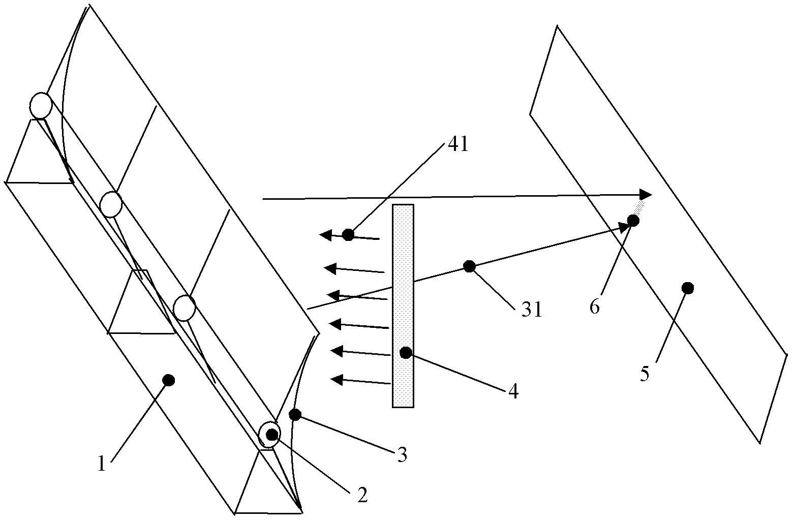
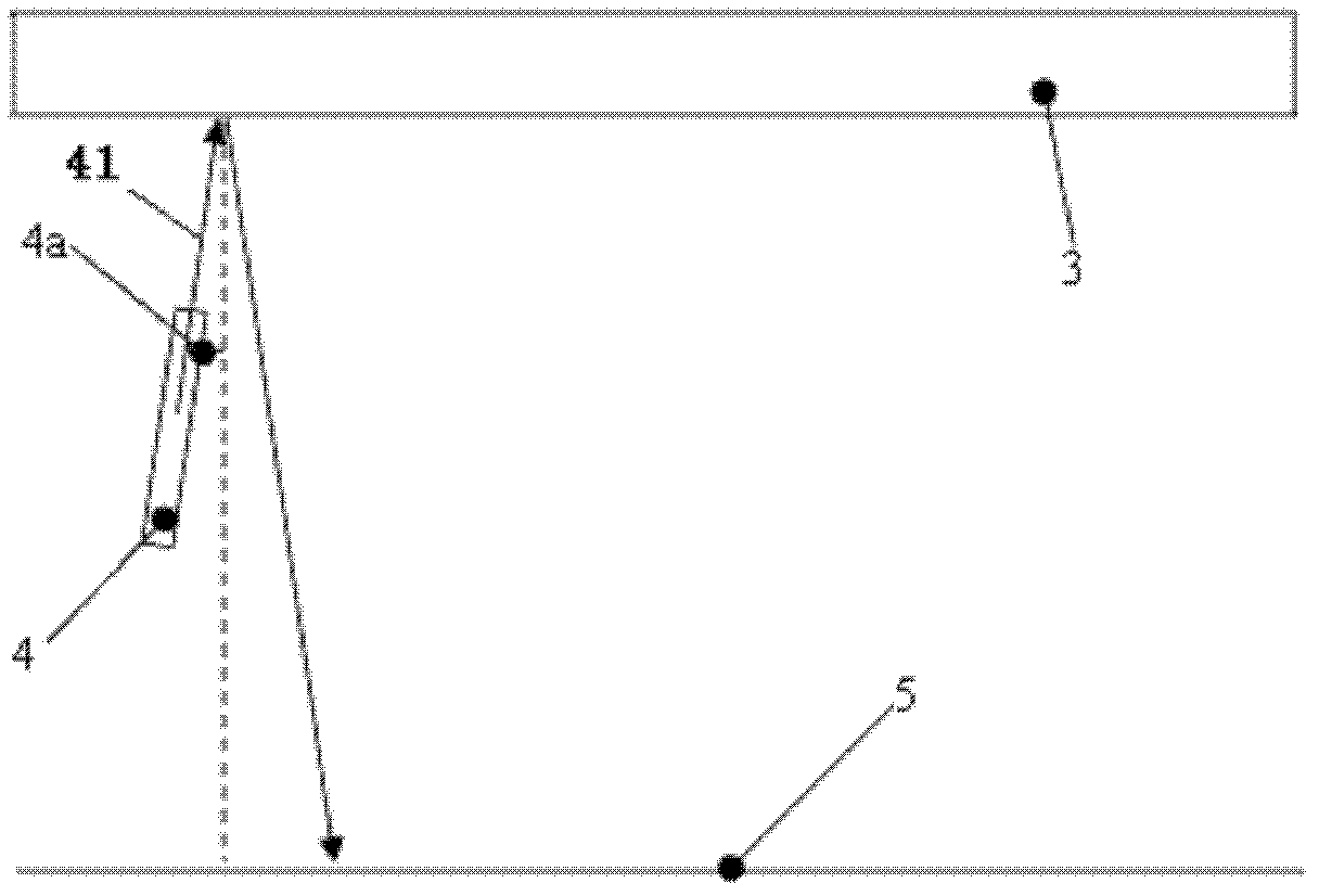
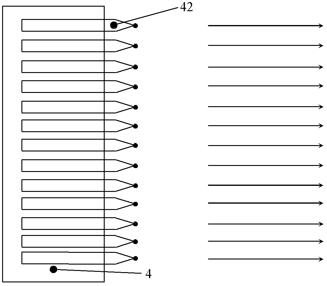
[0029] like figure 1 Shown, a kind of reflector calibration device of the present invention comprises support 1, is installed on support 1 and can rotate on support 1 reflector frame 2, is installed on the reflector 3 on reflector frame 2, The reflected light detection device 5 arranged in parallel with the reflection mirror 3, the parallel light source 4 arranged between the reflection mirror 3 and the reflection light detection device 5, the distance between the reflection mirror 3 and the reflection light detection device 5 and the actual use of the reflection mirror The distance from the reflector 3 to the focal point of the light is equal. The reflected light 31 after the parallel light 41 is reflected by the mirror 3 forms a light spot 6 on the reflected light detection device 5 .

[0030] If the distance between the reflector 3 ...


PUM


Abstract

The invention discloses a reflector adjusting device which comprises a reflector, a reflected light detector, and a parallel light source, wherein the reflected light detector and reflector are arranged in parallel, and the parallel light source is arranged between the reflector and the reflected light detector. The distance between the reflector and the reflected light detector is equal to the distance between the reflector and a light focus point in the actual use of the reflector. The reflector adjusting device disclosed by the invention is mainly applied in a linear sunlight focus system, so that reflection light spots of the reflector have better effects; and moreover, the adjusting operation of the reflector can be carried out indoors without being influenced by weather before on-site installation before the reflector is installed in site.

Description

technical field [0001] The invention relates to the technical field of mirrors, in particular to a mirror adjustment device. Background technique [0002] With the continuous development of economy and society, the demand for energy is increasing day by day. Fossil energy has increasingly serious pollution and non-renewable problems. It is imperative to develop clean and renewable energy. Solar energy is rich in reserves and is an environmentally friendly and clean renewable energy. The use of solar power or industrial heat utilization is an important form of energy utilization in the future. [0003] Since the direct radiation of sunlight is usually 500-2000W / m2 and the energy density is relatively low, when using sunlight, a concentrating device is usually used to gather sunlight to a certain point or surface to increase the radiant light at that position Strong, so that the use of sunlight to achieve higher efficiency. The solar thermal power generation system uses the...

Claims


Application Information

Patent Timeline
Patent Type & Authority Applications(China)
IPC IPC(8): G02B7/182G02B7/198
Inventor 许世森徐海卫郑建涛徐越刘冠杰刘明义裴杰李启明
Owner HUANENG CLEAN ENERGY RES INST
Why Eureka
Try Eureka