Method for manufacturing optical diaphragms and method for manufacturing stereoscopic displays

The technology of an optical film and its manufacturing method is applied in optics, optical components, nonlinear optics, etc., and can solve problems such as weak secondary alignment force, color shift, and image quality effects of stereoscopic displays, so as to improve color shift and improve The Effect of Stereoscopic Image Quality

Inactive Publication Date: 2014-12-03
CPT TECH GRP +1
View PDF9 Cites 0 Cited by
  • Summary
  • Abstract
  • Description
  • Claims
  • Application Information

AI Technical Summary

Problems solved by technology

However, due to the weak secondary alignment force of the second exposure, the result of the secondary alignment formed by the current technology is not good, and the image quality of the three-dimensional display is also affected. The emergence of partial problems

Method used


Image

  • Method for manufacturing optical diaphragms and method for manufacturing stereoscopic displays
  • Method for manufacturing optical diaphragms and method for manufacturing stereoscopic displays
  • Method for manufacturing optical diaphragms and method for manufacturing stereoscopic displays

Examples


Embodiment Construction

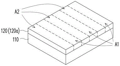
[0049] Figure 1A to Figure 1IIt is a schematic side view of the manufacturing process of the optical film according to an embodiment of the present invention.

[0050] Please refer to Figure 1A , coating the alignment liquid 120 on the first substrate 110, wherein the first substrate 110 has a first area A1 and a second area A2, and the first area A1 and the second area A2 are arranged alternately. In this embodiment, the alignment liquid 120 may be a photopolymerizable alignment material 120a, however, the present invention is not limited thereto. In addition, the method of coating the alignment liquid 120 on the first substrate 110 may be spin coating, slit coating or any other well-known method with common knowledge in this field, which will not be repeated here. detail.

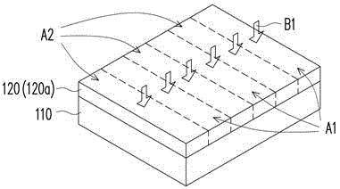
[0051] Please refer to Figure 1B , and then, the alignment liquid 120 is subjected to a pre-baking B1 process. It should be noted that the temperature and time control of the pre-bake B1 process wi...


PUM

PropertyMeasurementUnit
wavelengthaaaaaaaaaa
absorption wavelengthaaaaaaaaaa

Abstract

The invention relates to a method for manufacturing optical diaphragms. The method includes steps of coating alignment liquid onto a first substrate with a first area and a second area; irradiating polarized light to the alignment liquid on the first substrate to form optical alignment films, providing composite liquid crystal materials with reaction type liquid level materials and single materials and coating the composite liquid crystal materials on the optical alignment films; and sequentially irradiating first non-polarized light and second non-polarized light on the optical alignment films so that the single materials are reacted with the reaction type liquid crystal materials and the reaction type liquid crystal materials are solidified along a first alignment direction and a second alignment direction. The optical alignment films on the two areas respectively provided with the first alignment direction and the second alignment direction. The invention further provides a method for manufacturing a stereoscopic display by the aid of the method for manufacturing optical diaphragms.

Description

technical field [0001] The invention relates to a manufacturing method of a diaphragm and a manufacturing method of a display, in particular to a manufacturing method of an optical diaphragm and a manufacturing method of a three-dimensional display. Background technique [0002] In recent years, with the continuous advancement of display technology, users have higher and higher requirements for display quality (such as image resolution, color saturation, etc.) of the display. However, in addition to high image resolution and high color saturation, in order to meet the needs of users to watch real images, stereoscopic displays capable of displaying stereoscopic images have also been developed. [0003] The types of stereoscopic displays can be divided into stereoscopic and auto-stereoscopic according to whether the user wears specially designed head-mounted glasses. The working principle of the glasses-type stereoscopic display is mainly to use the display to send left and r...

Claims


Application Information

Patent Timeline
Patent Type & Authority Patents(China)
IPC IPC(8): G02F1/1337G02F1/1335G02B27/22
Inventor 苏峻纬连詹田
Owner CPT TECH GRP
Why Eureka
Try Eureka