Higher-order harmonic suppression device for X-rays in low energy section

A high-order harmonic suppression, X-ray technology, applied in installation, nonlinear optics, optics, etc., can solve the problems of large detuning angle, inconvenient operation, large loss of light intensity, etc.

Inactive Publication Date: 2012-07-18
SHANGHAI INST OF APPLIED PHYSICS - CHINESE ACAD OF SCI
View PDF0 Cites 4 Cited by
  • Summary
  • Abstract
  • Description
  • Claims
  • Application Information

AI Technical Summary

Problems solved by technology

[0004] But when the photon energy is low, the existing collimating mirror and focusing mirror are not enough to suppress high-order harmonics, because the principle of using collimating mirror and focusing mirror for harmonic suppression is to use the total reflection of X-rays. The loss of the fundamental wave of the method is small, but because the incident angle of X-rays on the collimating mirror and focusing mirror is small, only the high-order harmonics in the high-energy range (12-22.5keV) can be filtered out, and the low-energy range (3.5-12keV) The high-order harmonics cannot be suppressed and removed; the principle of using the twin crystal detuning method to suppress harmonics is to use the difference in Darwin (Darwin) width of different energies. Suppression still has a certain effect, but because the width of Darwin becomes larger, the detuning angle is required to be large, and the operation is inconvenient, and this method also filters part of the fundamental wave while removing high-order harmonics, resulting in a large loss of light intensity

Method used


Image

  • Higher-order harmonic suppression device for X-rays in low energy section
  • Higher-order harmonic suppression device for X-rays in low energy section
  • Higher-order harmonic suppression device for X-rays in low energy section

Examples


Embodiment Construction

[0031] Below, according to the accompanying drawings, preferred embodiments of the present invention are given and described in detail, so that the functions and features of the present invention can be better understood.

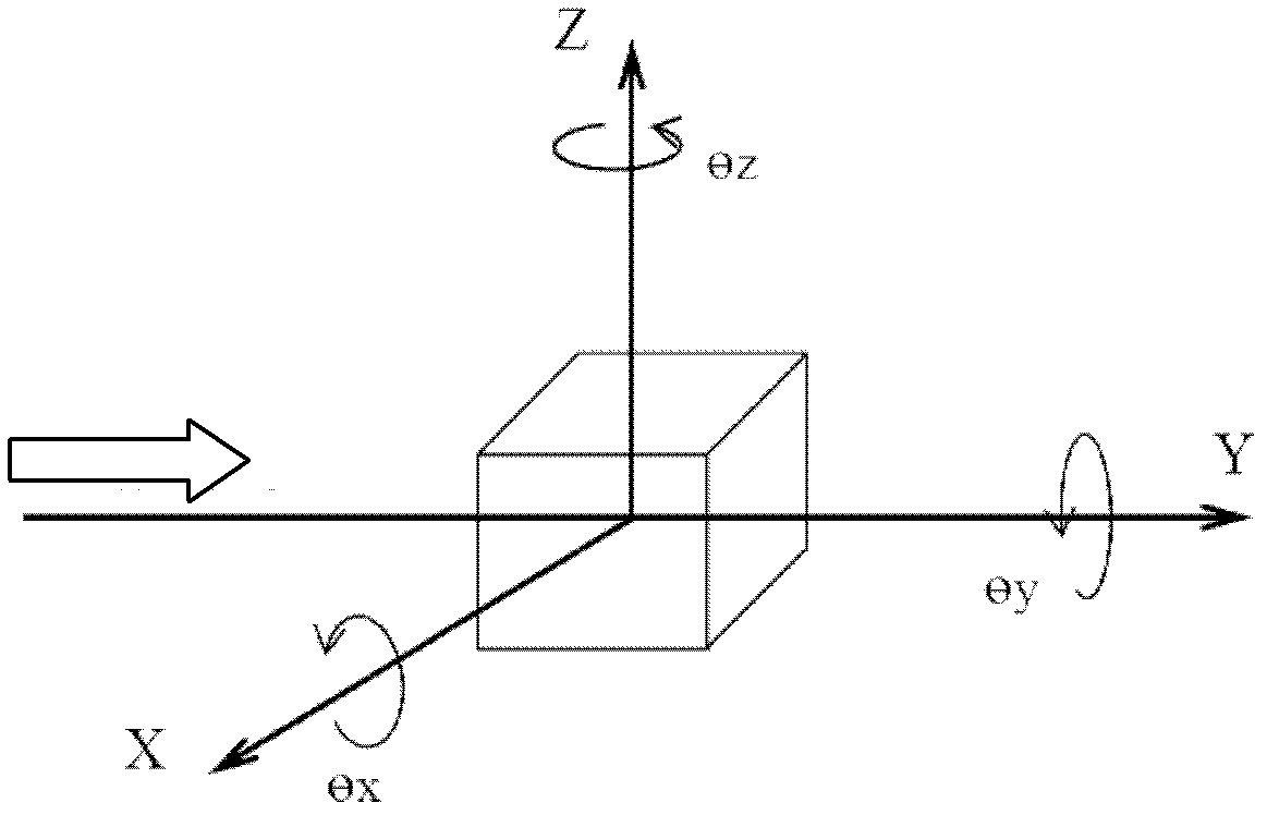
[0032] Such as figure 1 As shown, the definition of the coordinate system of the high-order harmonic suppression device for low-energy X-rays in the present invention will continue the definition of incident X-rays. The Y-axis is the horizontal coordinate axis along the incident direction of the X-ray; the Z-axis is the coordinate axis perpendicular to the horizontal plane where the X-ray is located, and the direction is upward; the X-axis is the coordinate axis perpendicular to the X-ray in the horizontal plane where the X-ray is located. The positive rotation direction around the coordinate axis satisfies the right-hand rule, where the pitch rotation (Pitch Rotation) is the rotation around the X axis (θ x ) angle; the roll angle (Roll Rotation) is the ro...


PUM


Abstract

The invention provides a higher-order harmonic suppression device for X-rays in low energy sections. The higher-order harmonic suppression device comprises a vacuum mirror box, at least one reflector, a clamping mechanism and an adjusting mechanism, the vacuum mirror box is provided with an X-ray inlet and an X-ray outlet, the reflectors are disposed between the X-ray inlet and the X-ray outlet, the surface of each reflector is provided with at least one reflecting area used for receiving and reflecting the X-rays, the clamping mechanism is used for clamping the reflectors, and the adjusting mechanism is connected to the lower side of the clamping mechanism. The higher-order harmonic suppression device for the X-rays in the low energy section has the advantages that positions and angles of the reflectors in the vacuum mirror box are adjusted by the aid of the adjusting mechanism, the X-rays are reflected by the reflecting areas of the surfaces of the reflectors for at least once, accordingly, higher-order harmonics of the X-rays in the low energy section are removed after the X-rays pass through a monochromator, and high-purity spectrum is provided for an XAFS (X-ray absorption fine structure) beam line station.

Description

technical field [0001] The invention relates to a high-order harmonic suppressing device, in particular to a high-order harmonic suppressing device for low-energy X-rays of an XAFS (X-ray absorption fine structure) beamline station. Background technique [0002] The XAFS beamline station is one of the first seven beamline stations built by Shanghai Light Source, which is mainly used for XAFS experiments. XAFS experiments have high requirements on the purity of spectra. Suppressing the high-order harmonic content of crystal monochromator is an effective method to obtain high-purity spectra. When the monochromator adopts Si(111) or Si(311) crystal, the 2nd harmonic can be eliminated, but the odd harmonic is not suppressed. In fact, the higher harmonic content is very small, as long as the third harmonic can be suppressed to meet the experimental requirements. [0003] For X-rays with higher photon energy, in the focusing mode, the existing collimating mirror and focusing mi...

Claims


Application Information

Patent Timeline
IPC IPC(8): G02F1/35G02B26/00G02B7/182
Inventor 魏向军傅远李丽娜薛松黄宇营姜政
Owner SHANGHAI INST OF APPLIED PHYSICS - CHINESE ACAD OF SCI
Why Eureka
Try Eureka