
Foot warping tackle

A pulley and foot-lifting technology, which is applied to overhead lines/cable equipment, cable laying equipment, and layout using take-up reels/photosensitive drums, etc., can solve the problem of heavy cable weight, increase insecurity factors, and increase security risks and other problems, to achieve the effect of convenient maintenance

Active Publication Date: 2012-07-18
DAZHOU POWER BUREAU SICHUAN ELECTRIC POWER +1
View PDF4 Cites 1 Cited by
  • Summary
  • Abstract
  • Description
  • Claims
  • Application Information

AI Technical Summary

Problems solved by technology

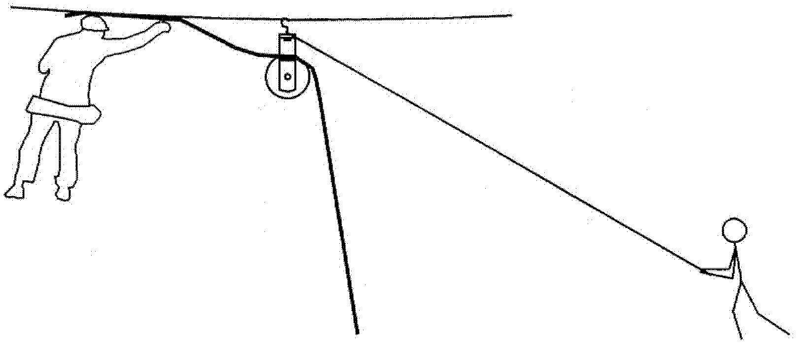
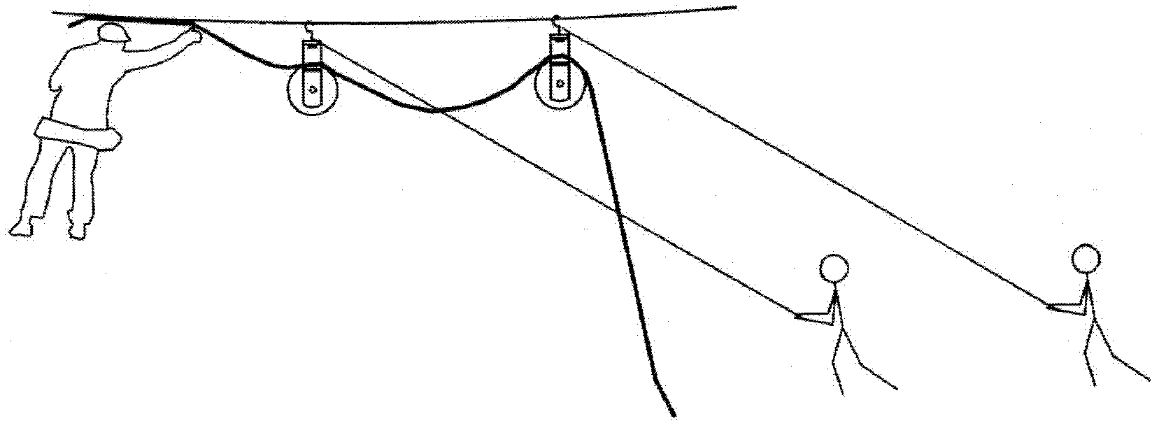
This kind of operation has the following disadvantages: First, if the cable is long, the wire diameter is large, and the weight of the cable itself is heavy, when the ground personnel pull the pulley, it will cause the steel strand and the high-altitude workers to shake violently, which increases the safety risk of the operators; The second is that although the cable can be pulled section by section by the pulley, it is still necessary to rely on the strength of the operator to hold the cable close to the steel strand with the strength of the operator's arm and then bind it to fix it. This will consume a lot of physical strength of the operator and increase unsafe factors; The decline in physical strength of personnel often makes the cable binding unsightly, and the cable rolls up and down on the steel strand, which affects the construction quality image of the power industry; fourth, the pulley hook directly slides on the steel strand with a load, destroying the galvanized layer of the steel strand, Reduced service life and increased security risks

Method used


Image

  • Foot warping tackle
  • Foot warping tackle
  • Foot warping tackle

Examples


Embodiment Construction

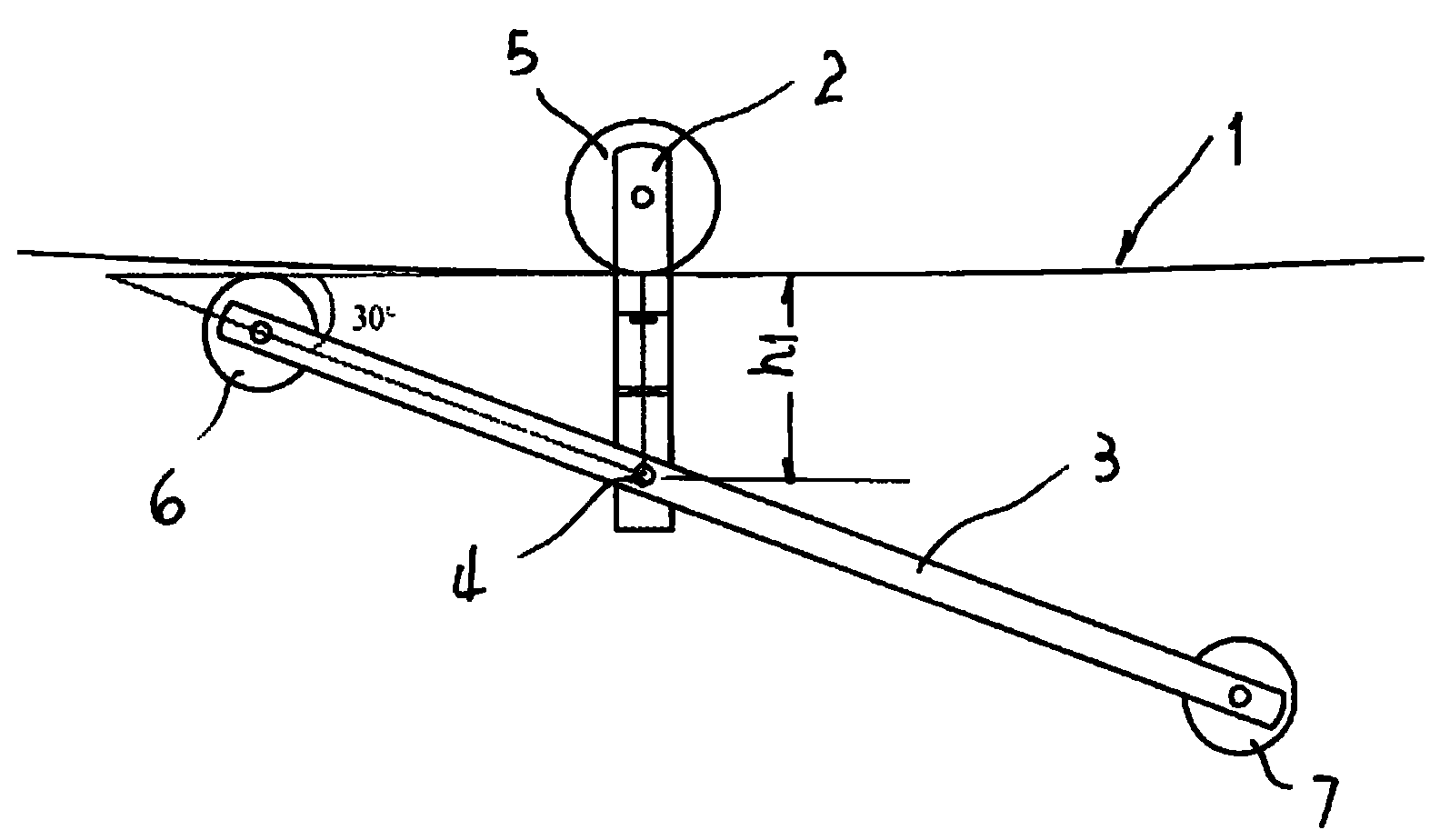
[0017] figure 2 , image 3 Shown is this sway block, which is used as a movable pulley 5 set on the steel strand 1 and is movably installed on the central shaft, which is fixed on two fixed arms 2; a movable shaft 4 is arranged at the lower part of the two fixed arms , a movable arm 3 is respectively fixed on the two ends of the movable shaft located on the outside of the two fixed arms, and the length from the movable shaft to the front end of the movable arm, that is, the forearm, is less than the length from the movable shaft to the rear end of the movable arm, that is, the rear arm. The front end of the arm is provided with a forearm pulley 6 used as a transmission cable, and the rear end of the two movable arms is provided with a rear arm pulley 7 used as a transmission cable. The movable pulley is located between the two fixed arms. figure 2 In the middle, the left is the front and the right is the back. The distance between movable shaft 4 and steel strand under mo...


PUM


Abstract

The invention provides a foot warping tackle, and belongs to overhead cable laying construction apparatus in the electric power industry. A movable pulley used for being sleeved on a steel strand to move is movably mounted on a middle shaft, wherein the middle shaft is fixed on two fixed arms; a movable shaft is arranged at the lower parts of the two fixed arms; two movable arms are respectively fixed at the two ends of the movable shaft, which are positioned on the outer sides of the two fixed arms; the length from the movable shaft to the front end of each movable arm, namely a front arm, is smaller than the length from the movable shaft to the back end of each movable arm, namely a back arm; a front arm pulley used for transmitting a cable is arranged at the front ends of the two movable arms; and a back arm pulley used for transmitting the cable is arranged at the back ends of the two movable arms. The foot warping tackle has the advantages that the front arms and the back arms, which are unsymmetrical, are adopted; and a right angled triangle is formed by utilizing the dead weight of the cable and the steel strand, so that the cable can be reliably borne and rapidly transmitted, the construction intensity is reduced and the construction safety is improved.

Description

technical field [0001] The invention relates to an overhead cable laying device in the electric power industry, in particular to a special laying device for binding and fixing cables on steel strands during construction. Background technique [0002] The current common method of laying overhead cables in the power industry is that the operators sit on the sliding wire board, fasten the safety belts, slide on the steel strands and bind and fix the cables, and the ground personnel use ropes to pull the cables by means of pulleys (see figure 1 and Picture 1-1 ). This kind of operation has the following disadvantages: First, if the cable is long, the wire diameter is large, and the weight of the cable itself is heavy, when the ground personnel pull the pulley, it will cause the steel strand and the high-altitude workers to shake violently, which increases the safety risk of the operators; The second is that although the cable can be pulled section by section by the pulley, it...

Claims


Application Information

Patent Timeline
IPC IPC(8): H02G1/02H02G1/06H02G11/02
Inventor 张迦勇李绍峰胡剑
Owner DAZHOU POWER BUREAU SICHUAN ELECTRIC POWER
Learn More