
Vehicle-mounted charger

An on-board charger and charger technology, applied in current collectors, electric vehicles, electrical components, etc., can solve the problems of low protection level, many equipment, low heat dissipation rate, etc., and achieve the effect of saving space

Inactive Publication Date: 2012-07-18
CHONGQING CHANGAN AUTOMOBILE CO LTD +1
View PDF5 Cites 15 Cited by
  • Summary
  • Abstract
  • Description
  • Claims
  • Application Information

AI Technical Summary

Problems solved by technology

However, for larger power chargers, their volume and heat dissipation are relatively large, and the heat dissipation through air cooling is slow and the heat dissipation rate is low, resulting in a low protection level
The forced air cooling method requires more equipment, resulting in a large area occupied, which makes the installation and layout difficult for the overall layout of the vehicle

Method used


Image

  • Vehicle-mounted charger
  • Vehicle-mounted charger
  • Vehicle-mounted charger

Examples


Embodiment Construction

[0021] The core of the present invention is to provide a vehicle-mounted charger to improve the heat dissipation rate and reduce the space occupancy rate at the same time.

[0022] In order to enable those skilled in the art to better understand the solution of the present invention, the present invention will be further described in detail below in conjunction with the accompanying drawings and embodiments.

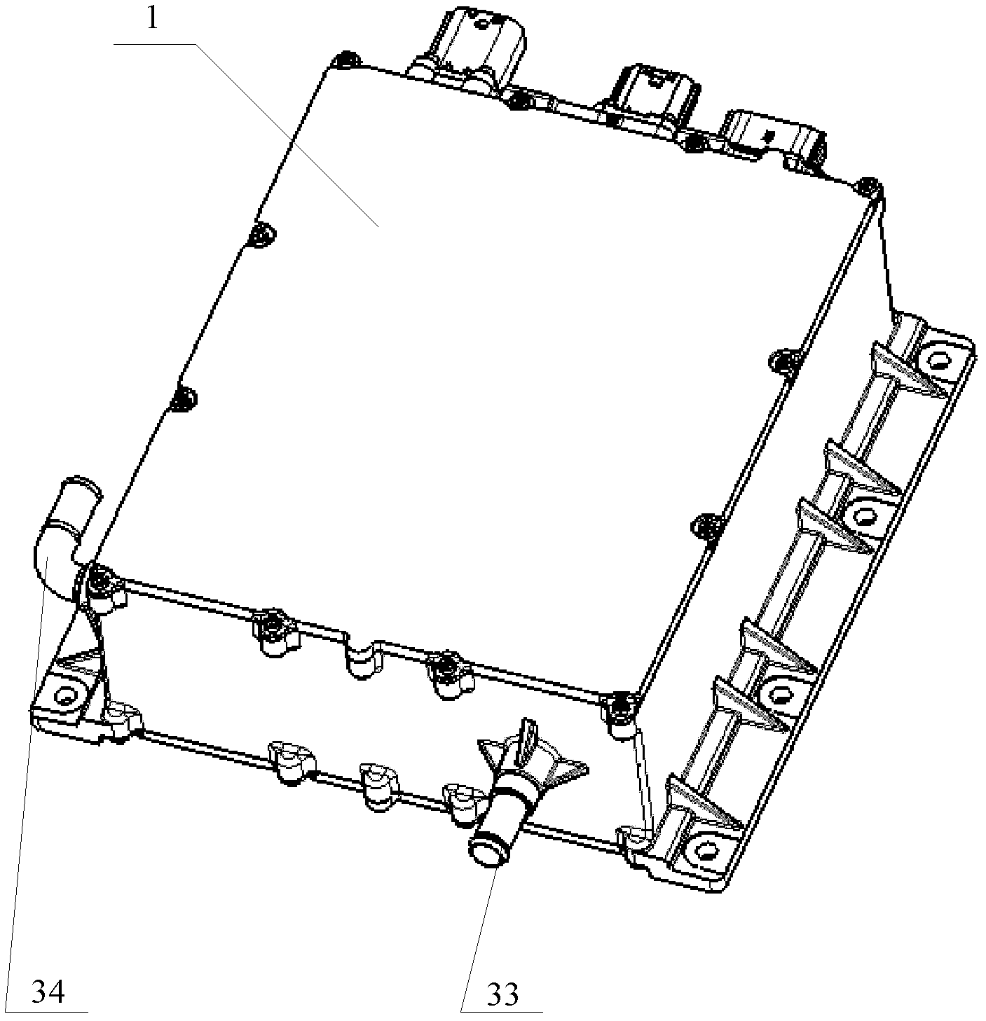
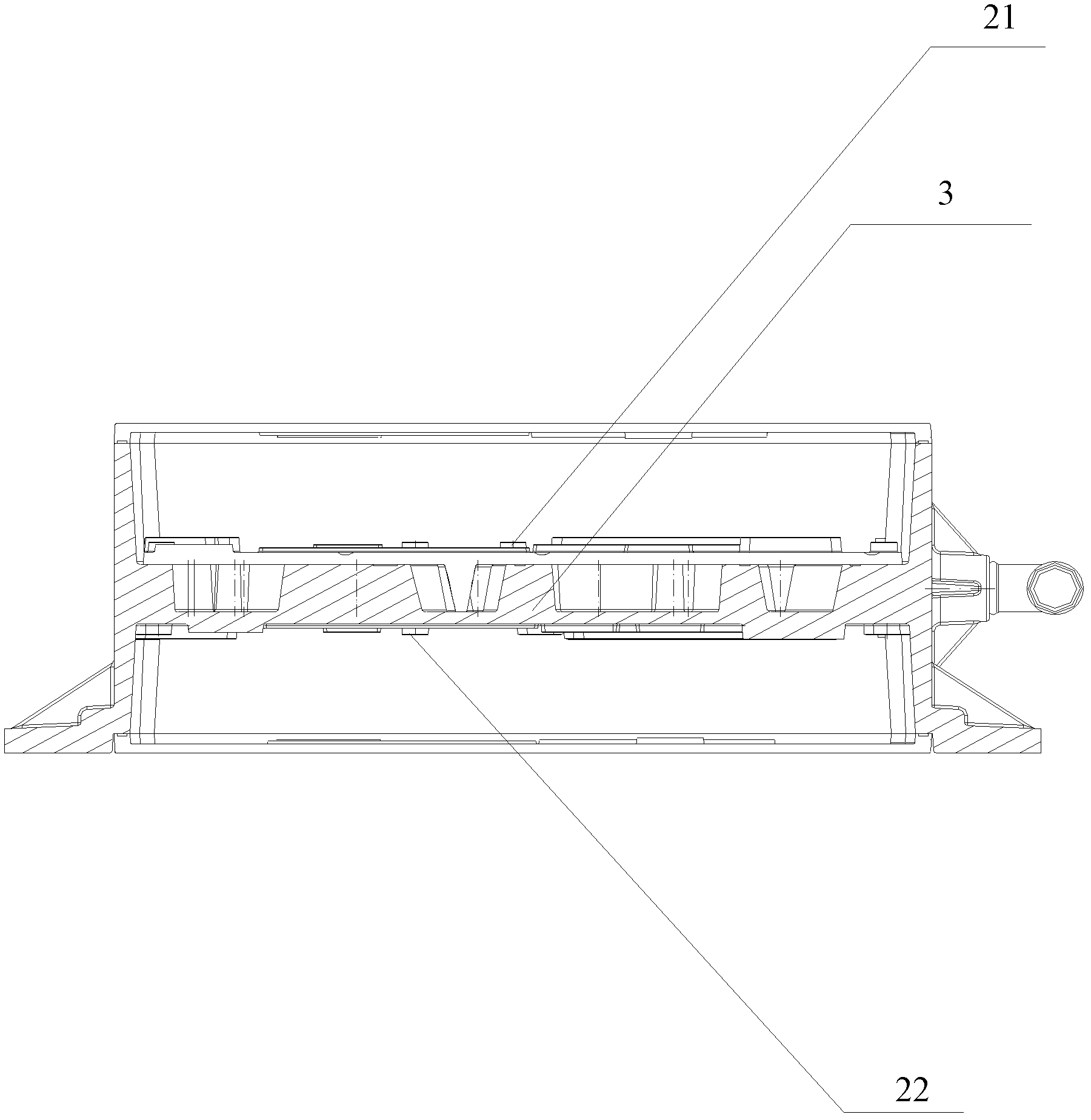
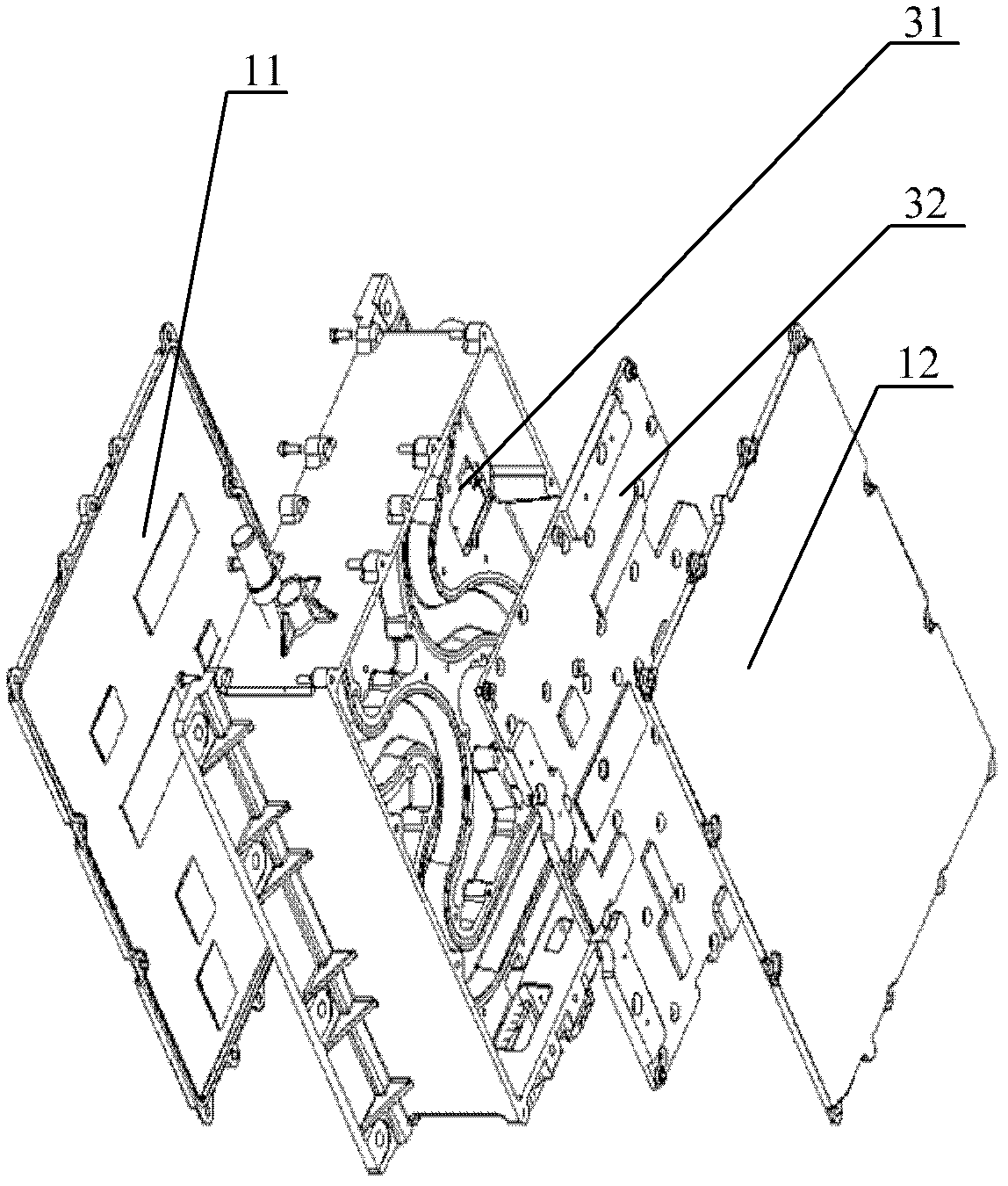
[0023] Please refer to Figure 1-Figure 4 ,in, figure 1 A structural schematic diagram of the charger body of the on-board charger provided by the embodiment of the present invention; figure 2 A schematic diagram of the internal structure of the on-board charger provided by the embodiment of the present invention; image 3 Schematic diagram of the structure of the on-board charger provided by the embodiment of the present invention; Figure 4 It is a schematic structural diagram of the lower cooling plate of the on-board charger provided by the embodiment of the pres...


PUM


Abstract

The invention discloses a vehicle-mounted charger. The vehicle-mounted charger comprises a charger body provided with a first power circuit board and a second power circuit board, and further comprises a liquid inlet and a liquid outlet which are formed on the charger body, and a cooling device provided with an upper cooling board and a lower cooling board, wherein the cooling device is arranged in the charger body; the first power circuit board is mounted on the upper cooling board; the second power circuit board is mounted on the lower cooling board; a cooling channel used for cooling liquid to circulate is arranged between the upper cooling board and the lower cooling board; and the two ends of the cooling channel are respectively communicated with the liquid inlet and the liquid outlet. The specific heat capacity of the cooling liquid is larger than that of air, so that heat of the vehicle-mounted charger can be rapidly dissipated through the circulation of the cooling liquid; and besides, the cooling device is integrated with the vehicle-mounted charger, that is, the cooling device is arranged in the vehicle-mounted charger, so that the space is effectively saved.

Description

technical field [0001] The invention relates to the technical field of electric vehicles, in particular to a vehicle charger. Background technique [0002] An electric vehicle charger is a device specially designed for charging the battery of an electric vehicle. It is a power conversion device with specific functions used when charging the battery. Therefore, as one of the important components of pure electric vehicles, the on-board charger must adapt to the environmental conditions of the vehicle. [0003] At present, the cooling method for electric vehicle chargers is through forced air cooling or natural air cooling. An air inlet and an air outlet are arranged on the trunk, so that the air in the vehicle compartment carries the heat emitted by the heat dissipation part of the electric vehicle charger and is discharged from the air outlet through the air exhaust duct. However, for a higher-power charger, its volume and heat dissipation are relatively large, and the heat...

Claims


Application Information

Patent Timeline
Patent Type & Authority Applications(China)
IPC IPC(8): H02J7/00H05K7/20
Inventor 刘太刚袁昌荣杜长虹焦志刚
Owner CHONGQING CHANGAN AUTOMOBILE CO LTD
Learn More