Valve bag sealing machine

A technology of valve bag and sealing machine, which is applied in packaging sealing/fastening, external support, transportation and packaging, etc. It can solve the problems of complex design, inability to feed materials in place at one time, and low quality of stitching, and achieves simple structure, reasonable design, The effect of uniform and stable feeding process

Inactive Publication Date: 2012-07-25
JINAN LIYU MACHINERY TECH
View PDF5 Cites 6 Cited by
  • Summary
  • Abstract
  • Description
  • Claims
  • Application Information

AI Technical Summary

Problems solved by technology

[0002] The valve bag automatic sealing machine needs to realize the purpose of automatic feeding and automatic sealing. The design of the automatic feeding mechanism on the existing sealing equipment is complicated, and there are problems that the feeding cannot be in place at one time and the material of the valve bag is easy to fold during the feeding process. The effect of automatic f

Method used


Image

  • Valve bag sealing machine
  • Valve bag sealing machine
  • Valve bag sealing machine

Examples


Embodiment Construction

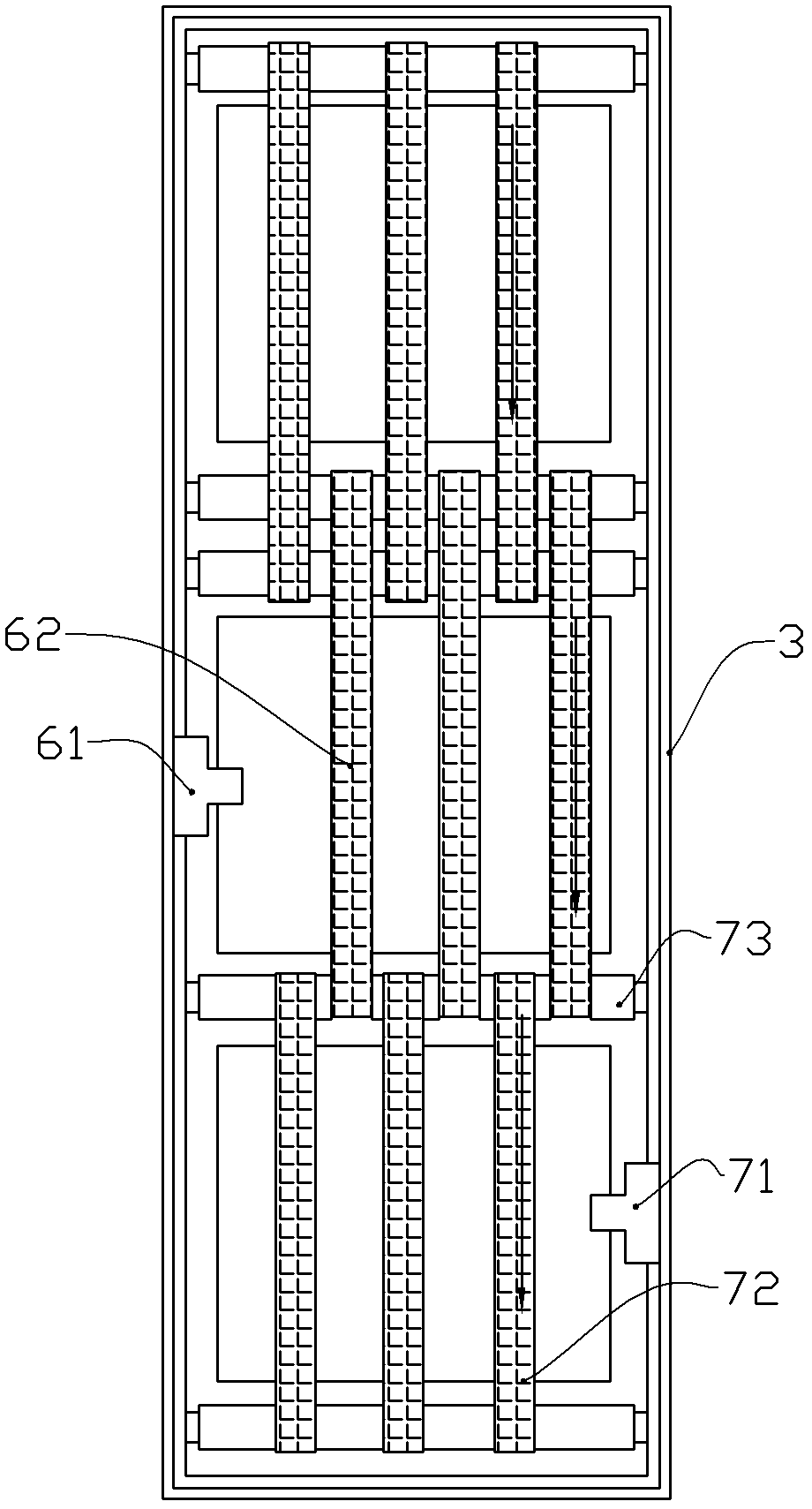
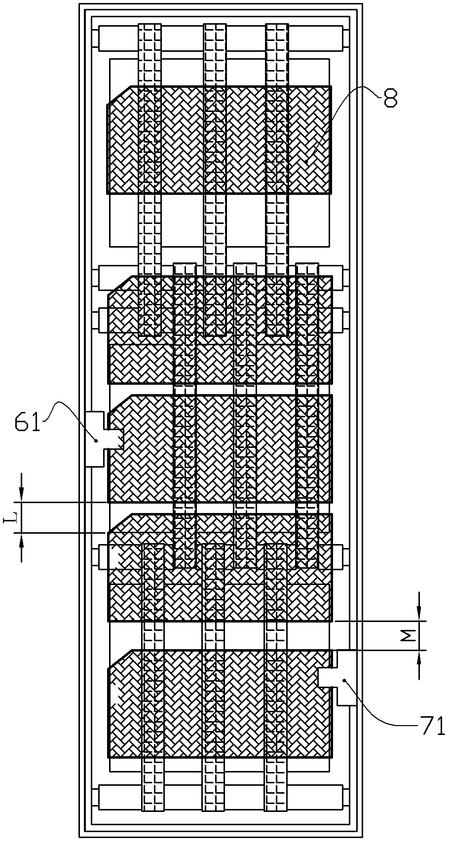
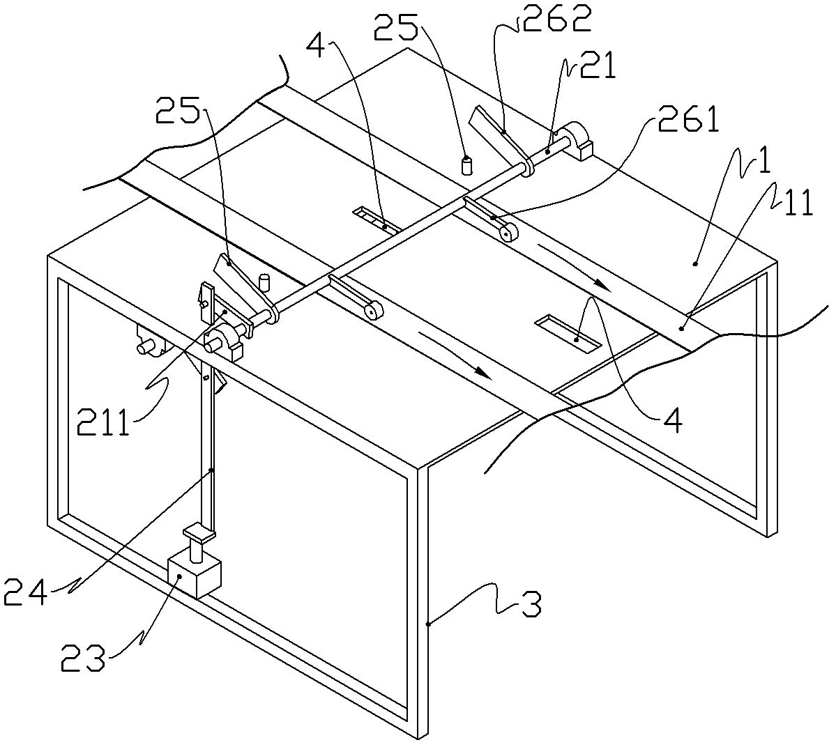
[0018] like Figure 1 ~ Figure 2 as shown, figure 1 The arrow in the figure indicates the transmission direction of the belt. A valve bag sealing machine includes a frame 3 and a feeding part, a sealing part, and a sealing bottom installed on the frame in sequence. The feeding part is used for uniform feeding, and only one piece is fed at a time The valve pocket blank is also provided with a valve pocket finishing mechanism at the end of the cover.

[0019] Feeding section comprises the first belt conveying device 11 and feeding mechanism, and the first belt conveying device is made up of front and rear rotating shaft, conveyor belt and driving motor, identical with existing belt conveying device.

[0020] like Figure 3 ~ Figure 7 As shown, the feeding mechanism is an auxiliary device of the valve bag sealing machine. It includes a stacking platform 1 and a feeding mechanism. The stacking platform 1 is a thin steel plate. The stacking platform 1 is welded on the upper side...


PUM


Abstract

A valve bag sealing machine is capable of automatically adjusting the distance between two valve bags in conveying, and sealing a top opening and a bottom opening according to the belt speed difference between a second belt conveying device and a third belt conveying device under equal sewing width and sewing effect. A feeding mechanism is reasonable in design, all actions can be controlled through one air cylinder, a pressure rod and an ejector match with each other to feed one single valve bag during feeding, and the feeding is even and stable.

Description

technical field [0001] The invention relates to a valve bag sealing device, in particular to a valve bag sealing machine. Background technique [0002] The valve bag automatic sealing machine needs to realize the purpose of automatic feeding and automatic sealing. The design of the automatic feeding mechanism on the existing sealing equipment is complicated, and there are problems that the feeding cannot be in place at one time and the material of the valve bag is easy to fold during the feeding process. The effect of automatic feeding Not ideal. [0003] At the same time, in the process of sealing the valve bag, since there is a gap, the length of the suture on both sides is different. When the existing common sealing machine seals, the length of the remaining thread is fixed, which results in a gap at both ends of the seal. The lengths of the thread ends are different, so the quality of the stitching is very low. Contents of the invention [0004] The object of the pre...

Claims


Application Information

Patent Timeline
IPC IPC(8): B65B51/07
Inventor 李靖宇
Owner JINAN LIYU MACHINERY TECH
Why Eureka
Try Eureka