
Cooling method used for segmented geometric adjustment of guide vanes of gas turbine

A gas turbine and cooling method technology, which is applied in the cooling of turbine/propulsion device, engine cooling, engine components, etc., can solve the problems of reducing the application difficulty of the segmented geometric adjustment method of guide vanes, and achieve the effect of preventing jamming

Active Publication Date: 2012-07-25
BEIHANG UNIV
View PDF6 Cites 5 Cited by
  • Summary
  • Abstract
  • Description
  • Claims
  • Application Information

AI Technical Summary

Problems solved by technology

[0005] The technical problem to be solved by the present invention is to overcome the deficiencies of the prior art, and provide a cooling method applied to the segmented geometric adjustment of the guide vane of a gas turbine, which can effectively solve the problem of the adjustment of the second half of the guide vane with less cooling air. Existing problems such as cooling and sealing reduce the difficulty of applying the guide vane segmental geometric adjustment method in turbines, especially high-pressure turbines

Method used


Image

  • Cooling method used for segmented geometric adjustment of guide vanes of gas turbine
  • Cooling method used for segmented geometric adjustment of guide vanes of gas turbine
  • Cooling method used for segmented geometric adjustment of guide vanes of gas turbine

Examples


Embodiment 1

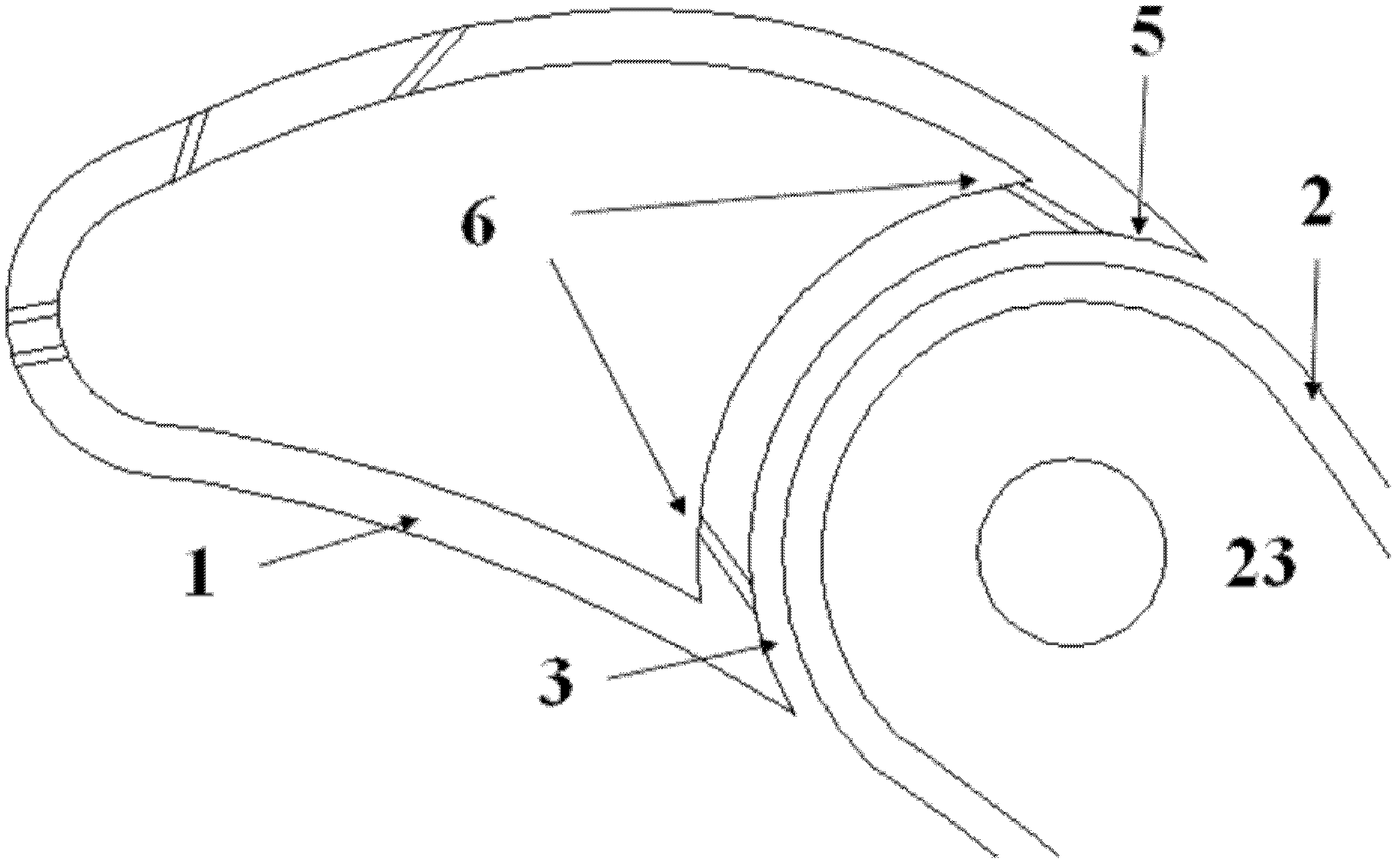
[0023] Embodiment 1: A cold air slot 6 is set up on the wall 5 where the front section 1 of the guide vane is in the gap 3 to spray the cold air. For the specific schematic diagram, see image 3 . A total of two rows of cold air slots 6 are arranged, one row is close to the side of the pressure surface 18 to spray cold air, and the other row is close to the side of the suction surface 19 to spray cold air. Since the pressure difference between the pressure side and the suction side of the gap 3 is very small, the pressure difference between the pressure side and the suction side of the gap 3 can be ignored, and the leakage flow from the pressure side to the suction side of the gap 3 and the corresponding countermeasures can be ignored. The cold air 7 eventually forms an adverse effect of an effective air film on the surface of the rear section 2, so the distances between the two rows of cold air slots are the same from their respective outlets. The width of the two rows of co...


PUM


Abstract

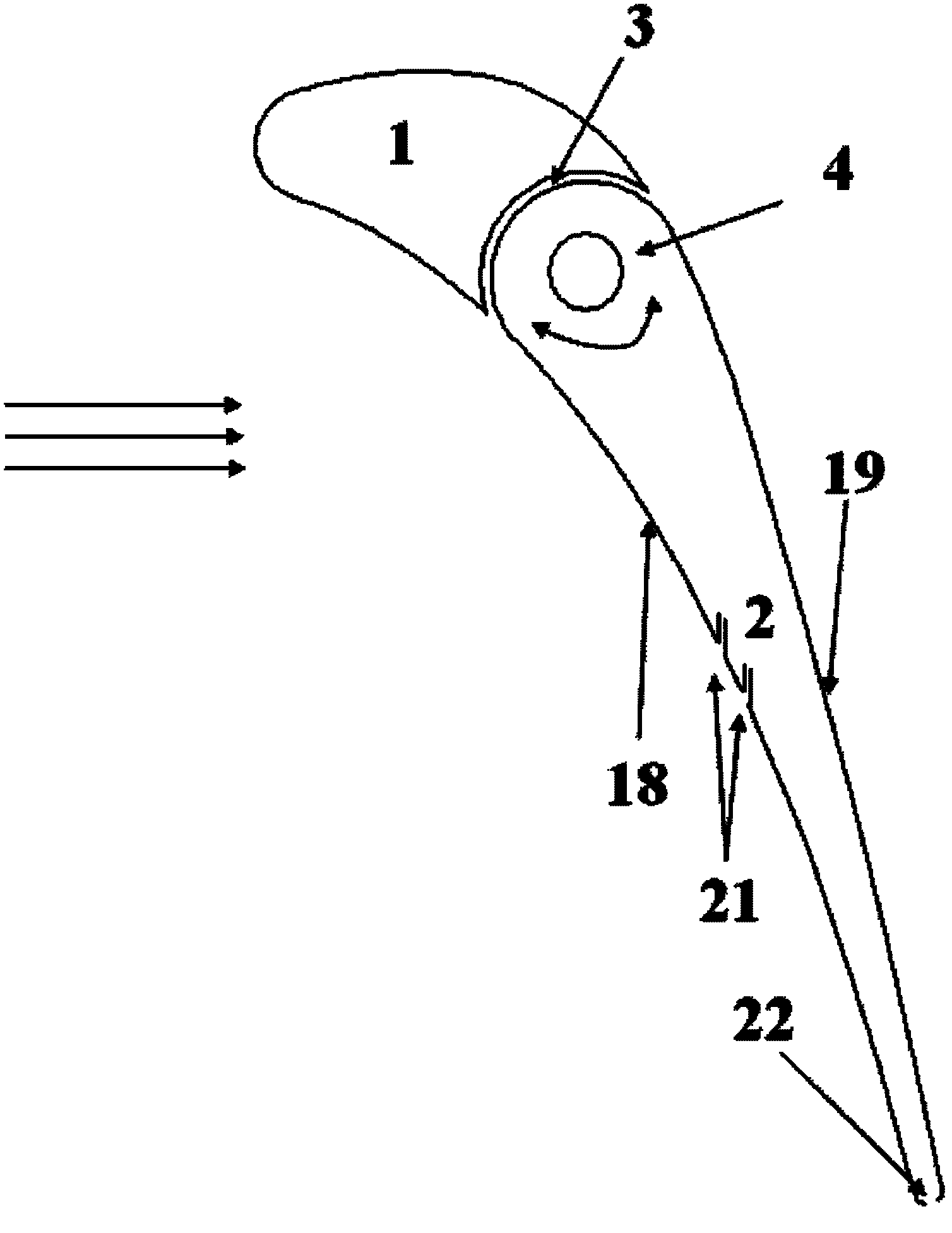
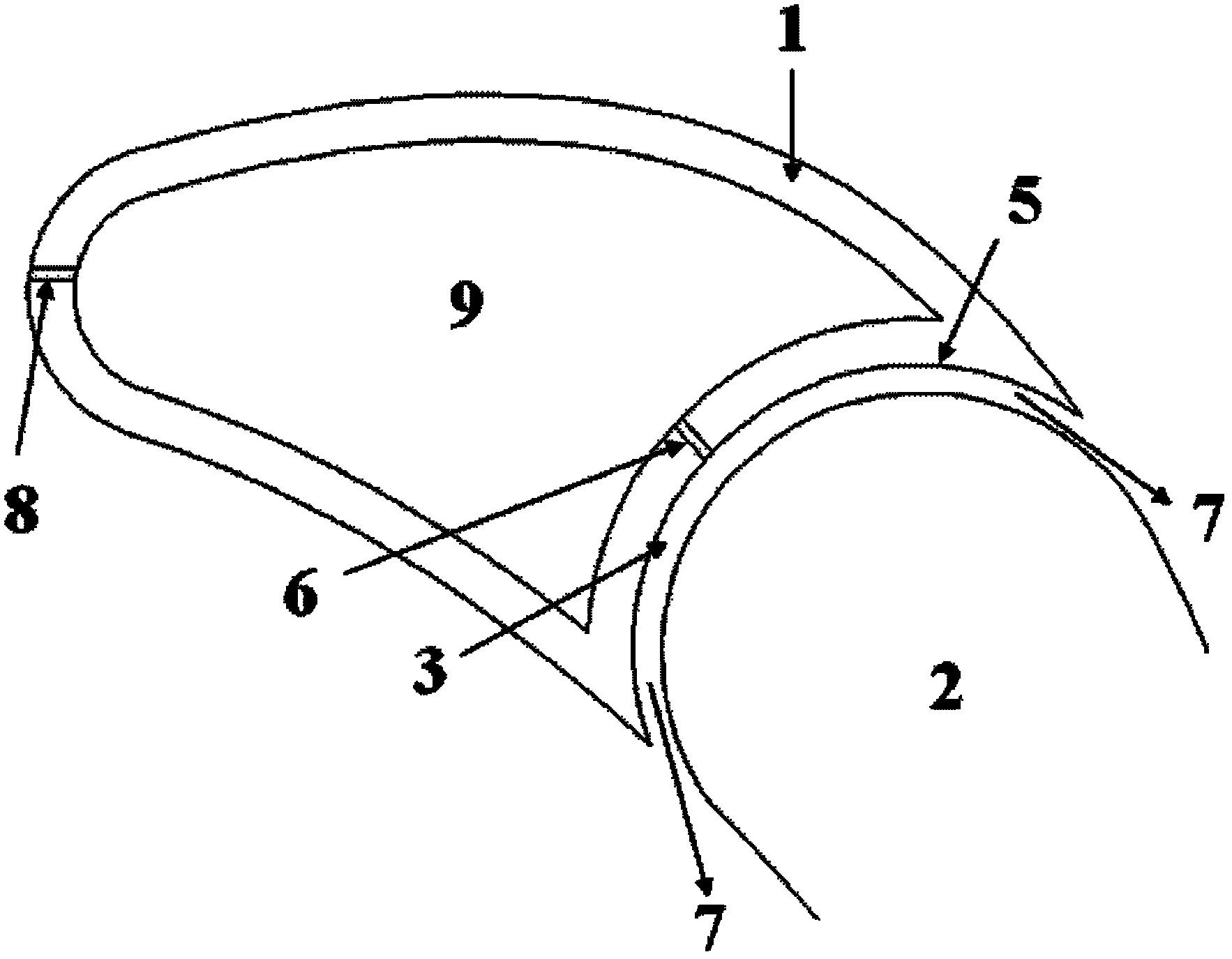
The invention discloses a cooling method used for the segmented geometric adjustment of guide vanes of a gas turbine. Cool air is sprayed to the surface of the rear section of the vane according to a certain angle from a front-section wall surface in an interval between the front section of the vane and the rear section of the vane, an effective cool air film is formed on the surface of the rear section of the vane, and simultaneously, the rear section of the vane can be cooled comprehensively by the combination of the air film cooling nearby a trailing edge and the crack seam cooling of the trailing edge, the cooling of the end surface of the rear section of the vane and the tight sealing of the intervals between the end surface of the rear section of the vane and a wheel hub as well as between the end surface of the rear section of the vane and a receiver can be realized by the cool air spraying of grooves of the end surfaces or the cool air spraying of a pressure surface nearby the end surface or a method of the combination of the cool air spraying of the grooves of the end surfaces and the cool air spraying of the pressure surface nearby the end surface; and the cooling and the tight sealing of the area can be realized effectively as the cool air is sprayed to the wall surfaces of the wheel hub and the receiver at the area nearby the junction of a shaft neck with the wheel hub and the receiver. According to the cooling method, the key areas in the segmented geometric adjustment can be cooled and sealed tightly and effectively with less cool air quantity, and the safe stability and the realizability of the geometric adjustment mode in the practical application can be improved.

Description

technical field [0001] The invention relates to a cooling method applied to the segmental geometric adjustment of guide vanes of gas turbines (the rear half of the guide vanes is adjustable), and belongs to the technical field of flow regulation of high and low pressure turbines in aeroengines or gas turbines of various uses. Background technique [0002] In the field of modern aviation, gas turbine engines used in advanced and practical supersonic transport aircraft or multi-purpose military fighters or aerospace aircraft must work in a wide range of flight Mach numbers and flight altitudes, which determines the working conditions of the engine The wide range of changes places high demands on the performance and stability of the engine. The traditional fixed geometry engine only has the best thermal performance near the design state, and the thrust of each state is obtained by adjusting the speed (thereby changing the air flow and pressure ratio), which will cause the flow ...

Claims


Application Information

Patent Timeline
Patent Type & Authority Applications(China)
IPC IPC(8): F02C7/12F02C7/18
Inventor 王鹏邹正平刘火星
Owner BEIHANG UNIV
Learn More