
A transfer pump for conveying solid-liquid mixture materials

A solid-liquid mixing and transfer pump technology, applied in the field of pump structure, can solve problems such as affecting transportation, pump body wear, blockage of pipelines, etc., to reduce the frequency of maintenance and replacement, increase service life, and reduce friction.

Active Publication Date: 2017-12-01
TAICANG SHUNDA MAGNETIC PUMP TECH
View PDF7 Cites 0 Cited by
  • Summary
  • Abstract
  • Description
  • Claims
  • Application Information

AI Technical Summary

Problems solved by technology

[0002] In the prior art, the transmission pump cannot pump the solid-liquid mixture containing a large amount of solids well, and it is prone to defects such as stuck inside the pump body and serious wear inside the pump body, resulting in frequent maintenance and replacement of the transmission pump, which consumes a lot of manpower and material resources , high production cost
Moreover, it is even more unable to meet the requirements of higher temperature transport materials with lower crystallization temperature
[0003] Substances with a lower crystallization temperature are transported in the pipeline, and the heat of the pipeline exposed to the air is easily lost, resulting in lower temperature and crystallization of the substance, which will block the pipeline and affect the transportation
Therefore, in the prior art, external foam sponges are often used for heat preservation. This method has disadvantages such as poor heat preservation effect and unstable transmission quality.

Method used


Image

  • A transfer pump for conveying solid-liquid mixture materials
  • A transfer pump for conveying solid-liquid mixture materials
  • A transfer pump for conveying solid-liquid mixture materials

Examples


Embodiment Construction

[0047] In order to make the object, technical solution and advantages of the present invention clearer, the present invention will be further described in detail below in conjunction with the accompanying drawings and embodiments. It should be understood that the specific embodiments described here are only used to explain the present invention, not to limit the present invention.

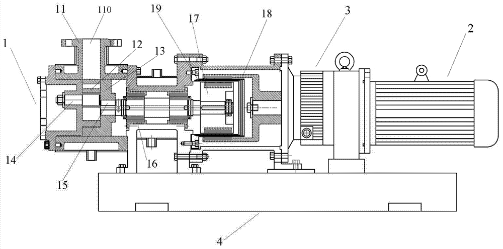
[0048] figure 1 Shown is a transfer pump 1 for conveying solid-liquid mixture materials, the transfer pump 1 includes a pump body 11, an inner rotor 12, an outer rotor 13, a pin shaft 14, a drive shaft 15, a bearing assembly 16, an inner magnetic coupling 17, The outer magnetic coupling 18 and the insulation isolation sleeve 19; the inner magnetic coupling 17 is connected to one end of the transmission shaft 15, the outer magnetic coupling 18 is arranged on the periphery of the inner magnetic coupling 17, and the insulation isolation sleeve 19 is arranged inside Between the magnetic coupling 17 an...


PUM


Abstract

Provided is a transfer pump (1) for conveying a solid-liquid mixture. The transfer pump comprises a pump body (11), an inner rotor (12), an outer rotor (13), a hinge pin (14), a transmission shaft (15), a bearing assembly (10), an inner magnetic coupling (17), an external magnetic coupling (18) and a thermal insulation and isolation jacket (19), wherein a cavity defined by the outer rotor, the transmission shaft and the bearing assembly is a high pressure cavity (111); a transmission shaft opening (112) is provided on the transmission shaft of the high pressure cavity near a material inlet (110), and the transmission shaft opening is used for allowing the solid-liquid mixture to enter the transmission shaft; and an internal hollow channel (113) is provided between one end of the transmission shaft near the thermal insulation and isolation jacket and the transmission shaft opening, and the internal hollow channel is used for conveying the solid-liquid mixture. The transfer pump enables the solid-liquid mixture pumped into the pump body gap and cavity to flow out of the pump body through internal channel circulation, with no blockage occurring to the the pump body; and a thermal insulation device is provided both inside and outside the pump body, and no phenomenon of pump body blockage due to material crystallization resulting from a decrease in material temperature occurs.

Description

technical field [0001] The invention relates to the technical field of pump structures, in particular to a transfer pump used for conveying solid-liquid mixture materials and an operation method thereof. Background technique [0002] In the prior art, the transmission pump cannot pump the solid-liquid mixture containing a large amount of solids well, and it is prone to defects such as stuck inside the pump body and serious wear inside the pump body, resulting in frequent maintenance and replacement of the transmission pump, which consumes a lot of manpower and material resources , high production cost. Moreover, it is even more unable to meet the transfer substances with lower crystallization temperature that have higher requirements on temperature. [0003] Substances with a lower crystallization temperature are transported in the pipeline, and the heat of the pipeline exposed to the air is easily lost, resulting in a drop in temperature and crystallization of the substanc...

Claims


Application Information

Patent Timeline
Patent Type & Authority Patents(China)
IPC IPC(8): F04C2/10F04C13/00F04C15/00
CPCF04C2/10F04C29/02
Inventor 顾建军顾秋林顾枫
Owner TAICANG SHUNDA MAGNETIC PUMP TECH
Learn More