
Distribution valve for pumping system, pumping system and engineering machinery

A pumping system and distribution valve technology, which is applied to the distribution valve of the pumping system and the field of construction machinery, can solve the problems of complex structure and high cost of space occupation, and achieve the effects of simplifying the control system, reducing weight, and facilitating installation and transportation

Active Publication Date: 2012-07-25
SANY HEAVY IND CO LTD (CN)
View PDF6 Cites 11 Cited by
  • Summary
  • Abstract
  • Description
  • Claims
  • Application Information

AI Technical Summary

Problems solved by technology

This related technology uses four oil cylinders to control four valve plugs to control suction and pumping, which also has the disadvantages of complex structure, space occupation and high cost

Method used


Image

  • Distribution valve for pumping system, pumping system and engineering machinery
  • Distribution valve for pumping system, pumping system and engineering machinery
  • Distribution valve for pumping system, pumping system and engineering machinery

Examples


Embodiment Construction

[0030] The specific implementation manner of the present invention will be described below in conjunction with the accompanying drawings. In the following description, many specific details are set forth in order to fully understand the present invention, but the present invention can also be implemented in other ways different from those described here, therefore, the present invention is not limited to the specific embodiments disclosed below limit.

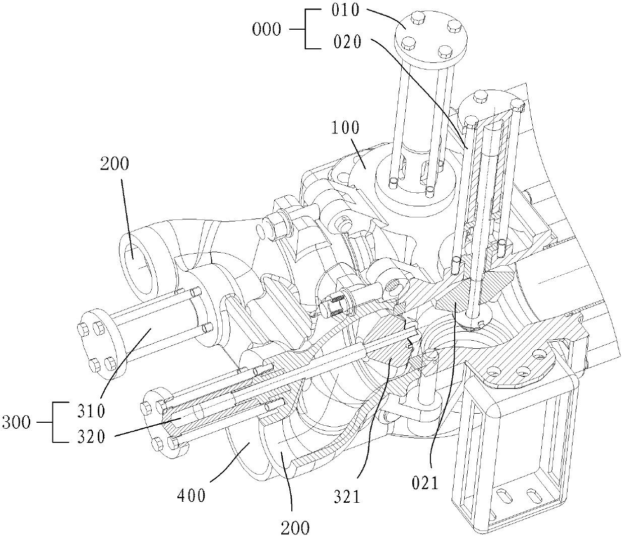
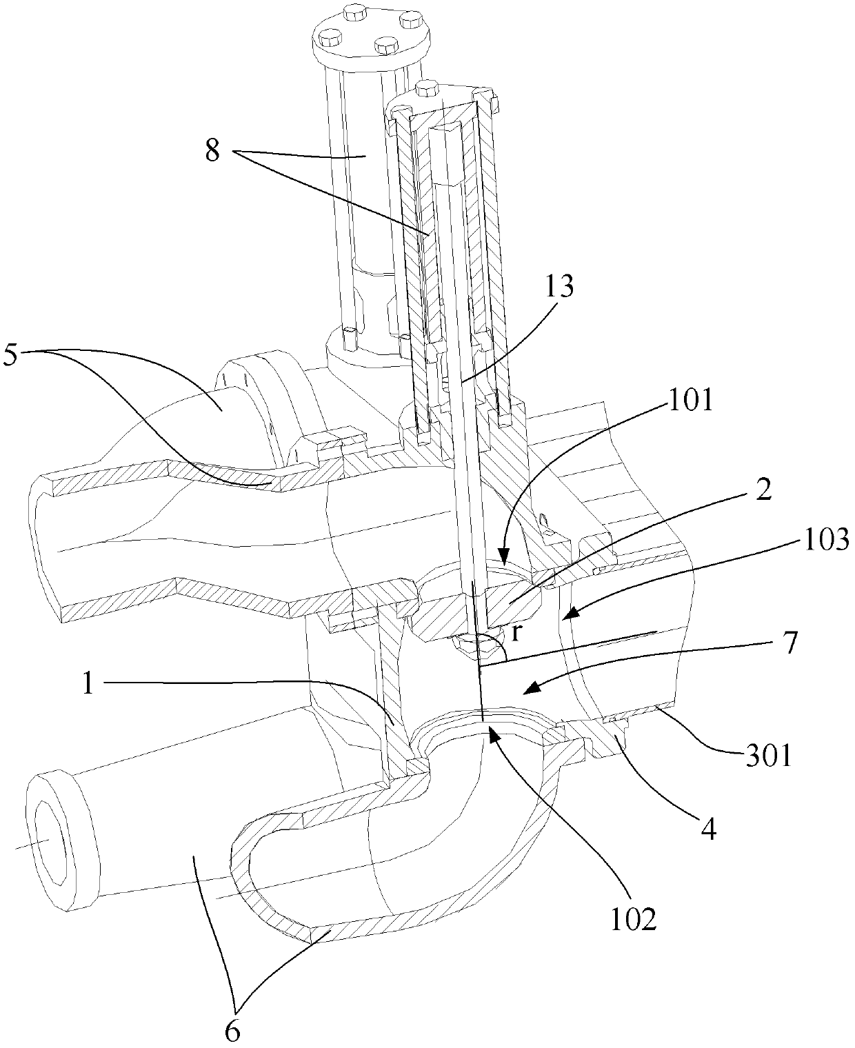
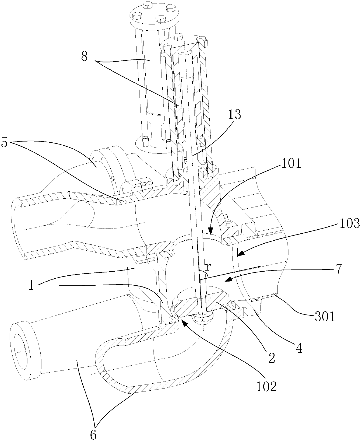
[0031] figure 2 It shows a schematic structural view of the distributing valve of the pumping system in the first working state in the first embodiment of the present invention; image 3 show figure 2 A structural schematic diagram of the distribution valve of the medium pumping system in the second working state; Figure 4 A schematic structural view of the valve body of the above-mentioned distributing valve of the present invention is shown; Figure 5 A schematic structural view of a pumping system applying the above d...


PUM


Abstract

The invention provides a distribution valve of a pumping system, which comprises a valve body. A valve cavity is positioned on the valve body, the valve body is provided with a valve a, a valve b and a valve c which are communicated with the valve cavity, a valve plug is positioned in the valve cavity, and under the action of a driving mechanism, the valve plug can seal the valve a and the valve b in alternative mode. The invention further provides a pumping system comprising the two distribution valves. By means of two valve plugs, the purpose that two delivery cylinders alternatively suck materials and pumping is achieved. The pumping system is simple in structure, reliable in distribution performance and capable of saving cost and installation space. Two sets of driving mechanisms are utilized to respectively drive the two valve plugs, thereby greatly simplifying a control system and lightening the weight of the whole machine. The invention further provides engineering machinery including the pumping system.

Description

technical field [0001] The present invention relates to dispensing valves, and more particularly, to a dispensing valve for a pumping system. The invention also relates to a pump, a conveying system and a construction machine. Background technique [0002] figure 1 The butterfly valve shown is the general grouting pump distributing valve form in the domestic and foreign markets, including a discharge cylinder 000, a valve body 100, a feed port 200, a feed cylinder 300 and a discharge port 400. When the pressure oil enters the rodless cavity of the left main oil cylinder, the piston rod pushes the left concrete piston to discharge the grout in the delivery cylinder. At this time, under the action of the left feed oil cylinder 310, the left feed valve plug closes the passage of the left conveying cylinder leading to the hopper, and the left discharge valve plug opens the left feed valve under the action of the left discharge cylinder 010. The passage of the side transfer cy...

Claims


Application Information

Patent Timeline
Patent Type & Authority Applications(China)
IPC IPC(8): F04B53/10
CPCF16K1/00F04B53/10F04B53/1007F16K11/044
Inventor 高杨蒋婷刘云
Owner SANY HEAVY IND CO LTD (CN)
Learn More