Liquid pump

A liquid pump and rotor technology, applied in the field of pumping equipment, can solve the problems of the rotor not being able to rotate and the rotor being easily stuck, and achieve the effects of noise elimination, long service life and convenient assembly

Active Publication Date: 2012-07-25
DONGGUAN ZHONGLONG PUMP TECH
View PDF5 Cites 3 Cited by
  • Summary
  • Abstract
  • Description
  • Claims
  • Application Information

AI Technical Summary

Problems solved by technology

Since this waste water contains a lot of metal shavings or other fine shavings, these metal shavings will be attracted by the magnet rotor in

Method used


Image

  • Liquid pump
  • Liquid pump
  • Liquid pump

Examples


Embodiment Construction

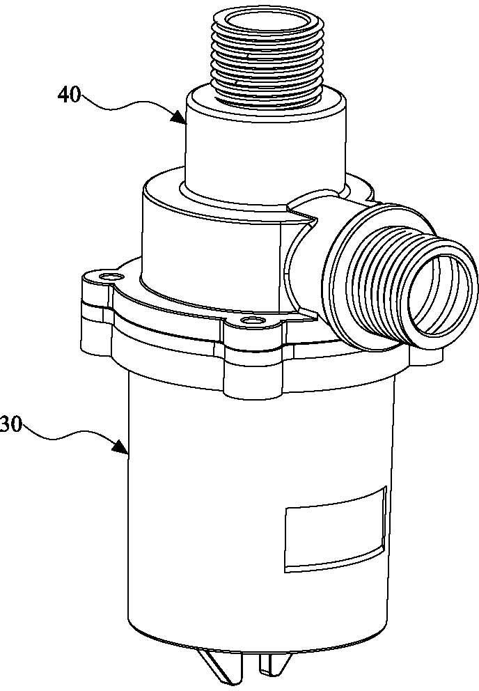
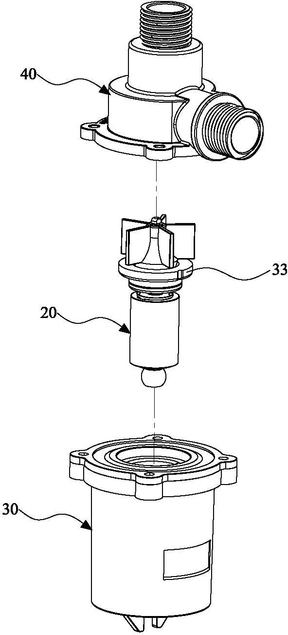
[0050] Please refer to figure 1 and figure 2 As shown, it shows the specific structure of the preferred embodiment of the present invention, including a stator assembly 10, a rotor assembly 20, a casing 30 and a pump cover 40, and the stator assembly 10 and the rotor assembly 20 are installed in the casing 30 , the pump cover 40 is fixed on the end of the housing 30 .

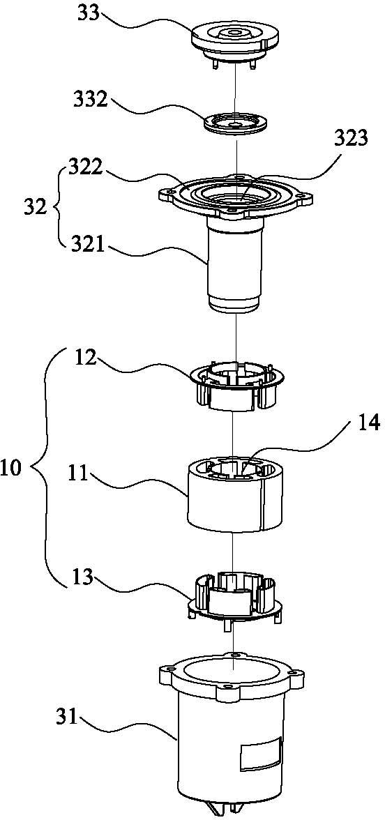
[0051] Among them, such as image 3 As shown, the housing 30 includes a motor casing 31 , a sealing spacer 32 and a sealing cover 33 . The stator assembly 10 includes a stator coil 11 , an upper jacket 12 and a lower jacket 13 .

[0052] The motor casing 31 is a hollow structure with an open upper end, and the sealing spacer 32 is installed in the hollow structure to form a second accommodating chamber 311 for installing the stator coil 11 (see Figure 5 ). The stator coil 11 is clamped by the upper jacket 12 and the lower jacket 13 and then installed in the second accommodating chamber 311 , and the uppe...


PUM


Abstract

The invention discloses a liquid pump, which comprises a case, a stator component, a rotor component and a pump cover. The case comprises a motor casing and a sealing separator with an upper opening, wherein the opening of the sealing separator is tightly sealed by a sealing cover to form a middle first containing chamber, the sealing separator is mounted in the motor casing to form a second containing chamber enclosing the first containing chamber, the stator component is mounted in the second containing chamber, the rotor component is rotatably inserted on the first containing chamber, the sealing cover is provided with an annular groove, and an annular stopper synchronously rotating with an impeller is correspondingly arranged in the groove in a matched manner and extends into the annular groove. Further, a sealing spacer is arranged at the position of a mandrel between the impeller and the sealing cover. By the aid of the scheme, multiple separation effects for metal chips in water flow can be achieved, so that the metal chips can be prevented from entering a rotor and blocking the rotor.

Description

technical field [0001] The invention relates to the technology in the field of pumping equipment, in particular to a liquid pump with convenient assembly and good stability. Background technique [0002] When machining metal parts with mechanical processing equipment (such as lathes, milling machines, drilling machines, planers, etc.), it is necessary to use coolant (cooling water) to cool the processing position, and at the same time wash away many metal fines that are processed. Next, the waste water with metal fines will be concentrated into a liquid storage pool or tank, and then the waste water will be pumped away and filtered by a liquid pump for recycling. Because this waste water contains a lot of metal shavings or other fine shavings, when using a common pump for suction, these metal shavings will be attracted by the magnet rotor in the motor and stick to the rotor, which will easily block the rotor and prevent the rotor from rotating. Therefore need to use a kind ...

Claims


Application Information

Patent Timeline
IPC IPC(8): F04D13/06F04D29/00F04D29/08
Inventor 黄武源黄志荣
Owner DONGGUAN ZHONGLONG PUMP TECH
Why Eureka
Try Eureka