Impeller modified structure of chemical process pump

A technology for process pumps and impellers, which is applied to parts, pumps, and pump components of pumping devices for elastic fluids, and can solve problems such as loss, reduced pump efficiency, and reduced pump efficiency, achieving less friction loss and reduced Efficiency loss, effect of reducing friction area

Inactive Publication Date: 2010-04-07
XIANGYANG WU ER WU PUMP IND
View PDF0 Cites 5 Cited by
  • Summary
  • Abstract
  • Description
  • Claims
  • Application Information

AI Technical Summary

Problems solved by technology

The semi-open impeller structure designed by the closed impeller design method has strict requirements on the gap between the pump body and the pump body. Once the gap is too large, the liquid will flow into the pump chamber and flow out of the pump body through the action of the blades, and a small part of the liquid will Through the gap between the vane and the pump wall of the pump body, the flow returns to the impeller inlet, and then enters the vane flow channel again. The loss caused by the backflow of the liquid in the pump cavity reduces the pump efficiency.
At the same time, the sharp turn of the blade 1 and the small area between the blades 1 cause the secondary flow loss caused by partial turbulence and the friction loss of the cover plate 2 disc, which reduces the efficiency of the pump.

Method used


Image

  • Impeller modified structure of chemical process pump
  • Impeller modified structure of chemical process pump
  • Impeller modified structure of chemical process pump

Examples


Embodiment Construction

[0019] specific implementation

[0020] Below in conjunction with accompanying drawing and embodiment the present invention will be further described;

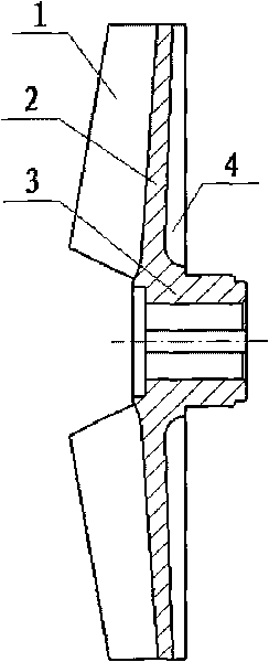
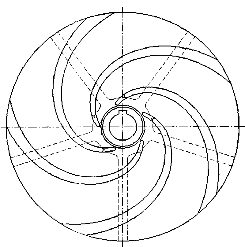
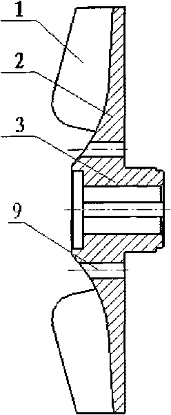
[0021] Such as image 3 , Figure 4 As shown, a modified impeller structure of a chemical process pump according to the present invention includes blade 1 , cover plate 2 , hub 3 ; peripheral equipment includes pump cover 6 , mechanical seal 7 , pump shaft 8 , and impeller nut 10 . Among them: blade 1 adopts equivariant angle logarithmic spiral to draw the profile line, the thickness of the blade gradually increases along the profile line from the inlet end to the outlet end, the inlet end is 6 mm, and the outlet end is 9 mm; at the blade outlet, the end point of the profile line is the cut Make a circular arc uniform hollow cover with a radius of 20mm, retain part of the cover, and evenly distribute six Φ6mm balance holes 9 with a center diameter of Φ50mm on the cover; the hub is a ring-shaped body, and the connection with ...


PUM


Abstract

The invention relates to an impeller structure of a pump, in particular to an impeller structure of a chemical process pump, which belongs to the field of mechanical fluid. The impeller structure comprises blades, cover plates and a hub, wherein molded lines of the blades are drawn by using equal changeable angle logarithmic spiral lines, and the thickness of the blades gradually increases from an inlet end to an outlet end along the molded lines; the outline on the left side of the cover plates is in smooth and backward inclined extension, and the thickness of the cover plates gradually increases from the inlet end to the outlet end along the smooth and backward inclined extension; an outlet of the blades is uniformly distributed with hollow cover plates, and a part of the cover plates is retained; each cover plate is uniformly distributed with balance holes for balancing a part of axial force; and the hub is a ring body and is provided with a key slot in the junction with an axis. The components are connected in the following relation: the blades, the cover plates and the hub are cast into a whole body to form an impeller; the blades are uniformly distributed on the cover plates; and the hub is arranged on the back side of the cover plates. The impeller structure is to improve the efficiency of the chemical process pump and prevent fins from abrading a pump cover near the impeller so as to ensure the use efficiency and reduce the running maintenance cost of the chemical process pump.

Description

technical field [0001] The invention relates to an impeller structure of a pump, in particular to an impeller structure of a chemical process pump, belonging to the field of mechanical fluids. Background technique [0002] In the field of chemical industry, chemical process pumps are mainly used to transport various corrosive media with low particle content, and in some special working conditions, to transport media that are prone to crystallization, suspended solids and sediment particles. In the pump device, the closed impeller is more efficient than the corresponding open impeller, but it is easy to block when transporting media such as crystallization and suspended solids and sediment particles. Therefore, open impellers are widely used in this working condition. The impeller is the most important working element of the pump. It is matched with the pressurized water chamber to obtain high-efficiency flow, head and service efficiency; in the prior art, the impeller is a s...

Claims


Application Information

Patent Timeline
Patent Type & Authority Applications(China)
IPC IPC(8): F04D29/22F04D29/24
Inventor 梁晨阳吴志宏童继勇裴有志
Owner XIANGYANG WU ER WU PUMP IND
Why Eureka
Try Eureka