Positioning and splicing device of indicating grating

A technology of indicating grating and bonding, which is applied in the direction of using optical devices, measuring devices, instruments, etc., can solve the problems of the influence of precision, the inability to accurately adjust the position of the indicating grating, and the difficulty in ensuring the reliability of the grating ruler measurement mechanism. Achieve the effect of improving reliability and precision, convenient operation and reducing adjustment time

Active Publication Date: 2012-07-25
CHANGCHUN INST OF OPTICS FINE MECHANICS & PHYSICS CHINESE ACAD OF SCI
View PDF5 Cites 29 Cited by
  • Summary
  • Abstract
  • Description
  • Claims
  • Application Information

AI Technical Summary

Problems solved by technology

The traditional craft means is to operate entirely with the eyes and hands of the master installer, so that the position of the indicating grating cannot be adjusted very accurately, making it difficult to guarantee the reliability of the entire grating ruler measurement mechanism, and the accuracy will also be affected to a certain extent

Method used


Image

  • Positioning and splicing device of indicating grating
  • Positioning and splicing device of indicating grating
  • Positioning and splicing device of indicating grating

Examples


Embodiment Construction

[0014] The specific embodiments of the present invention will be further described below in conjunction with the accompanying drawings.

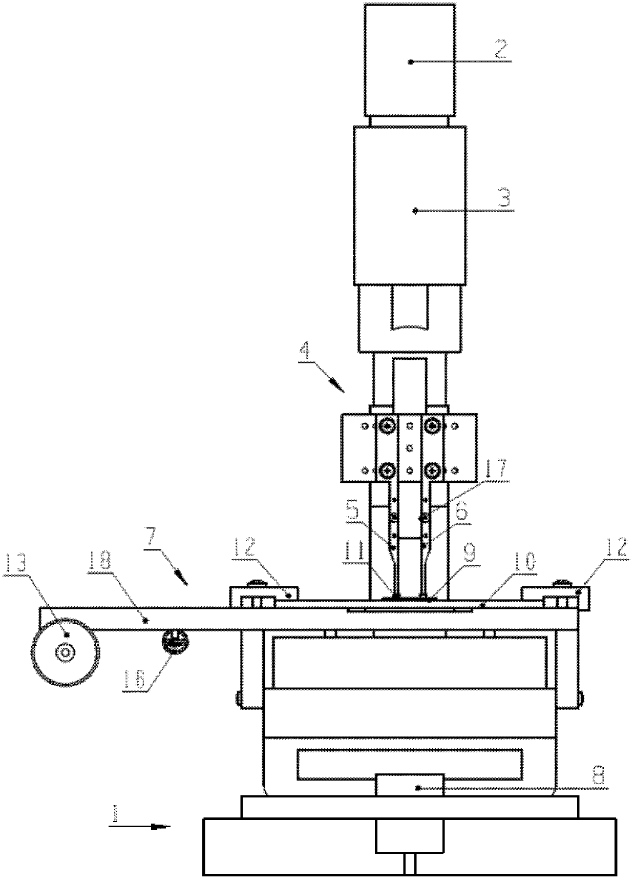
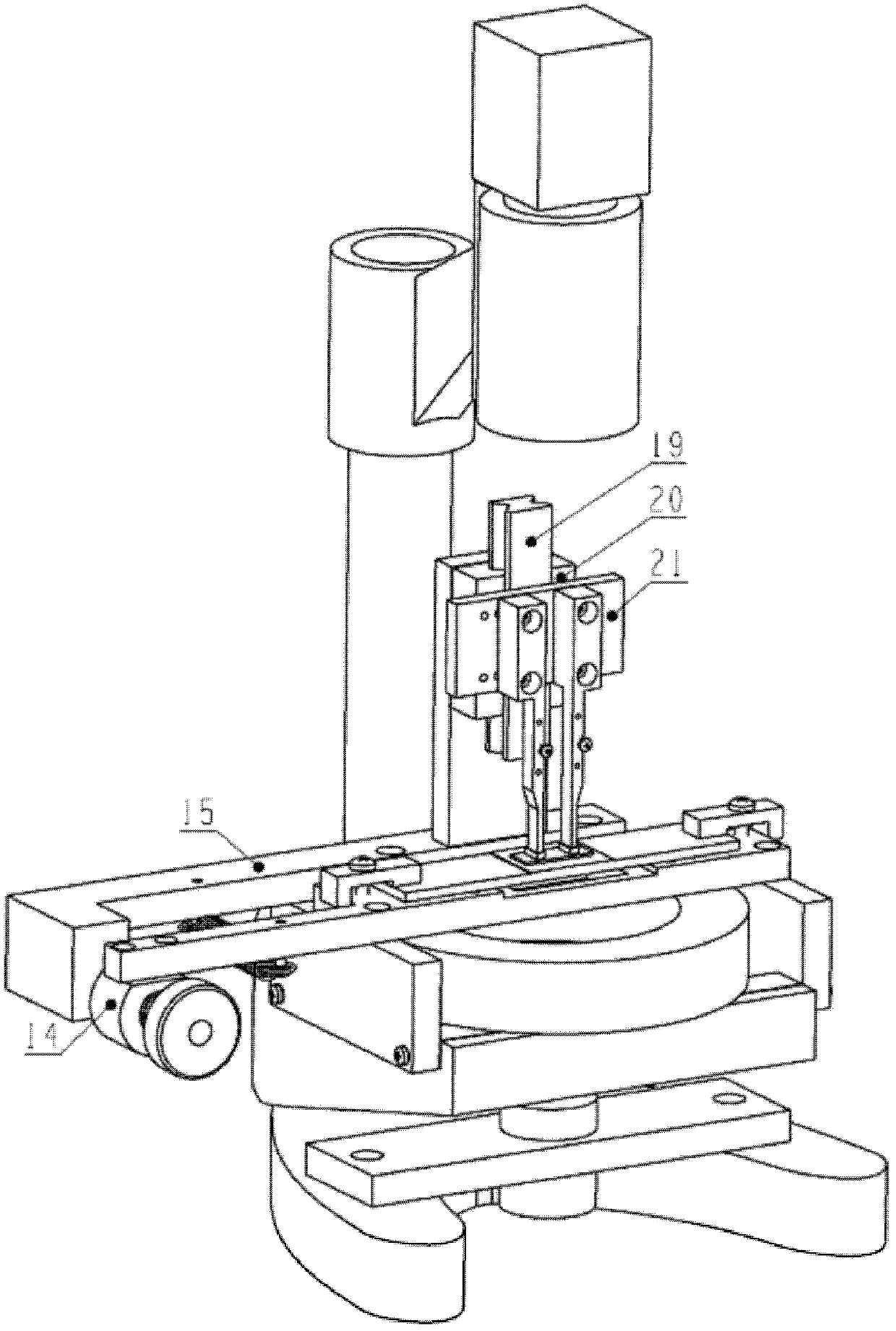
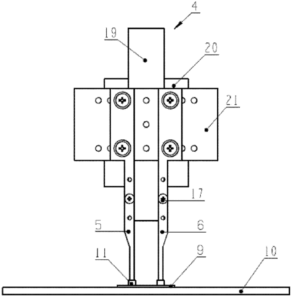
[0015] Such as figure 1 and figure 2 As shown, the positioning and bonding device of the indicating grating is composed of a support mechanism 1, a CCD2, an objective lens 3, a guide rail mechanism 4, a left pressing pin 5, a right pressing pin 6, an adjusting mechanism 7, a light source 8, an indicating grating 9 and a main grating 10 composition. CCD2 is located at the top of the positioning bonding device, the lower end of CCD2 is connected with objective lens 3, CCD2 and objective lens 3 are fixed on the top of support mechanism 1, light source 8 is fixed on the bottom of support mechanism 1, guide rail mechanism 4 is arranged on the bottom of objective lens 3 Below, the guide rail mechanism 4 is fixed on the adjustment rod 15 of the adjustment mechanism 7, the left pressing needle 5 and the right pressing needle 6 are fixed on the pr...


PUM


Abstract

The invention provides a positioning and splicing device of an indicating grating, belongs to the technical field of photoelectric measurement, and aims to conveniently and accurately position the indicating grating before the indicating grating is spliced on an indicating grating carriage. The device comprises a supporting mechanism, a charge coupled device (CCD), an objective lens, a guide rail mechanism, a left pressing needle, a right pressing needle, a regulating mechanism, a light source, the indicating grating and a main grating, wherein the lower end of the CCD is connected to the objective lens; the guide rail mechanism is arranged below the objective lens and is fixedly arranged on the regulating mechanism; the left and right pressing needles are fixedly arranged on the guide rail mechanism; the indicating grating is pressed on the main grating by the left and right pressing needles; the main grating is fixedly arranged on the regulating mechanism; the regulating mechanism is fixedly arranged on a middle seat of the supporting mechanism; the light source is arranged at the bottom end of the supporting mechanism; and light emitted by the light source irradiates on the main grating and the indicating grating and is then imaged on the CCD via the objective lens. The positioning and splicing device is applied to the structure mounting process of a grating ruler, and the reliability of a grating ruler measuring mechanism is guaranteed.

Description

technical field [0001] The invention relates to a positioning bonding device for an indicating grating, and belongs to the technical field of photoelectric measurement. Background technique [0002] In the field of precision measurement and displacement control, the use of grating as a benchmark is internationally recognized as the most practical, economical and reliable technical measure to obtain high precision. The grating ruler measuring mechanism is a representative product to achieve this approach, and is widely used in various machine tools, electromechanical equipment, and automated measuring equipment. [0003] The grating scale used on the CNC machine tool is composed of the main grating and the indicating grating. The main grating is glued on the scale shell, and the indicating grating is glued on the indicating grating carriage of the reading head. When the feed axis of the CNC machine tool moves, the scale The shell and the reading head move relative to each ot...

Claims


Application Information

Patent Timeline
Patent Type & Authority Applications(China)
IPC IPC(8): G01B11/00
Inventor 杨帆张吉鹏孟辉乔栋曾琪峰
Owner CHANGCHUN INST OF OPTICS FINE MECHANICS & PHYSICS CHINESE ACAD OF SCI
Why Eureka
Try Eureka