
Method for rapidly monitoring deformation by aid of ground-based three-dimensional laser scanner

A three-dimensional laser and scanner technology, applied in the direction of optical devices, instruments, measuring devices, etc., can solve problems such as the inability to achieve rapid feedback of monitoring results, and achieve the effect of saving time

Active Publication Date: 2012-07-25
北京天下图数据技术有限公司
View PDF2 Cites 44 Cited by
  • Summary
  • Abstract
  • Description
  • Claims
  • Application Information

AI Technical Summary

Problems solved by technology

Although the application of ground-based 3D laser scanners in the field of monitoring has gradually developed, there are currently no methods and technologies for laser scanning monitoring technology in practical engineering applications in China, and a systematic and reliable monitoring data analysis method has not yet been formed. The monitoring methods of data and indoor analysis and processing methods cannot achieve the purpose of rapid feedback of monitoring results
A fast and efficient method for deformation measurement based on ground-based 3D laser scanners has not yet been formed

Method used


Image

  • Method for rapidly monitoring deformation by aid of ground-based three-dimensional laser scanner
  • Method for rapidly monitoring deformation by aid of ground-based three-dimensional laser scanner
  • Method for rapidly monitoring deformation by aid of ground-based three-dimensional laser scanner

Examples


Embodiment Construction

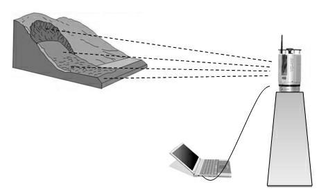
[0019] The method includes a method for rapidly monitoring deformation of an area-type three-dimensional laser scanner.

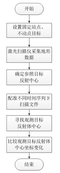
[0020] (1) First set up a suitable fixed site and fixed point target, and fix the ground-based 3D laser scanning on the pile dial. Use a threaded screw to fix the instrument, scale marks, and place the scanner to align with the scale. When the scanner is fixed on the pile, use a threaded bolt. The unthreaded end is buckled into the dial, and the threaded end is buckled under the instrument. The instrument chassis and Pile Dial Engagement. After determining the fixed site, paste 3-5 circular reflectors with a diameter of 5cm within 30m around the fixed site where the instrument is placed for calibration, and ensure that these reflectors are fixed throughout the monitoring process.

[0021] (2) The laser scanner collects topographic data: the purpose of rough scanning is to find the tracking target position and correct the reflector more easily and quickly; ...


PUM

PropertyMeasurementUnit
Diameteraaaaaaaaaa

Abstract

The invention relates to a method for rapidly monitoring deformation and controlling a measured deformation value within instrument precision by the aid of a ground-based three-dimensional laser scanner serving as a measuring instrument through instruction fixing technology. The method includes the steps: (1) fixing the three-dimensional laser scanner onto an observation pillar, setting a fixed point reference target and attaching a reflector onto an observation object; (2) rapidly scanning the observation object by the aid of the three-dimensional laser scanner; (3) searching a reflection center of the reference target; (4) registering scan files in different time series according to the reflection center of the reference target; (5) finding a coordinate of a reflector center of the observation object after registering; and (6) comparing the change of the coordinate in the different time series. The method is applicable to rapidly monitoring deformation of slope failure at a deformation stage, slope excavation and various deformation bodies.

Description

technical field [0001] The invention relates to the fields of surveying and mapping and remote sensing monitoring. Background technique [0002] With the continuous development of 3D laser scanning measurement technology, 3D modeling research and computer hardware environment, the application fields of ground-based 3D laser scanners are becoming more and more extensive, such as manufacturing, cultural relic protection, reverse engineering, computer game industry, film special effects, Digital city construction, engineering deformation monitoring, etc., especially in the high-precision real-time acquisition of large-scale digital elevation models, urban 3D model reconstruction, and geographic information acquisition in local areas, etc., have become an important aspect of photogrammetry and remote sensing technology. Replenish. At present, the application of 3D laser scanners is mainly focused on terrain surveying and mapping, 3D model building, cultural relic protection and...

Claims


Application Information

Patent Timeline
IPC IPC(8): G01B11/16
Inventor 不公告发明人
Owner 北京天下图数据技术有限公司
Learn More