Device for measuring negative skin friction of pile soil

A measuring device and technology of negative frictional resistance, which is applied in the field of devices for measuring the performance of soil with piles, can solve the problems of limited container space, low soil load value, limited height and sand density, etc., and achieve sufficient placement space , The settlement of the soil is obvious, and the effect of ensuring accuracy

Inactive Publication Date: 2012-07-25
SOUTHEAST UNIV
View PDF5 Cites 41 Cited by
  • Summary
  • Abstract
  • Description
  • Claims
  • Application Information

AI Technical Summary

Problems solved by technology

[0004] At present, the problem of soil loading has not been solved well in the domestic and foreign pile foundation negative friction laboratory tests
Existing studies mostly use high-pressure air or sand loading, but both methods have obvious defects
For example, judging from several cases of negative friction resistance tests using high-pressure air to load soil, although a large soil loading value (>100kPa) can be achieved, it needs to be carried out in a sealed container, except for the cost of test equipment. Outside the Philippines, due to the limited container space, it is impossible to carry out pile top loading and erection of related testing instruments
Therefore, the test is mostly limited to the study of the settlement difference inside and outside the pile group under the action of uniform soil load, and the research content is single.
The soil loading method does not need to be carried out in a closed container by using the method of sand pile loading, which has a large space for the installation of test instruments and can collect multiple test data. However, because the height of the test box and the density of sand and soil are limited, the simulation The pile load value of the soil is low (about 10kPa), resulting in low pile negative friction resistance value, which seriously affects the test results

Method used


Image

  • Device for measuring negative skin friction of pile soil
  • Device for measuring negative skin friction of pile soil
  • Device for measuring negative skin friction of pile soil

Examples


Embodiment Construction

[0022] The technical solution of the present invention will be described in detail below in conjunction with the accompanying drawings.

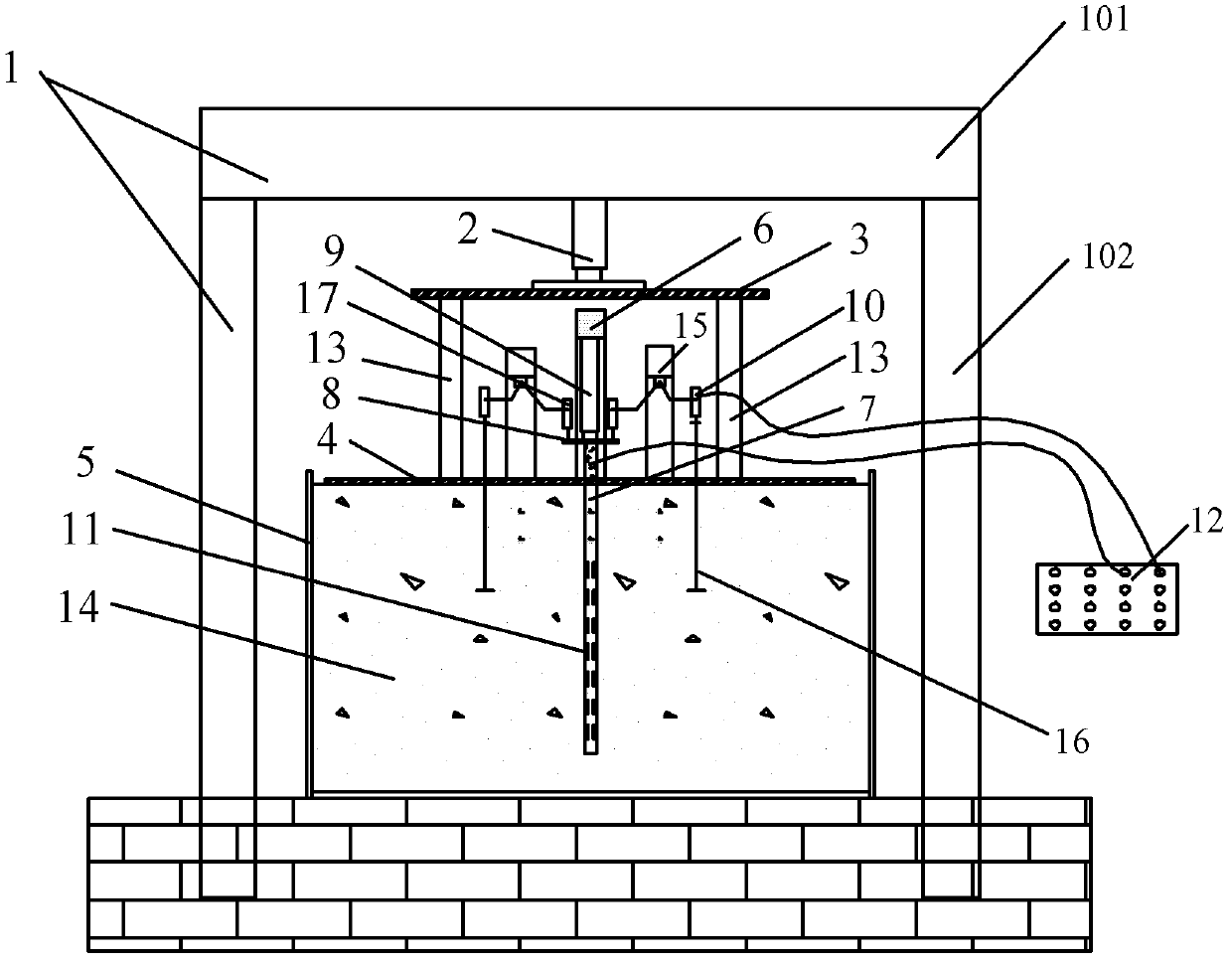
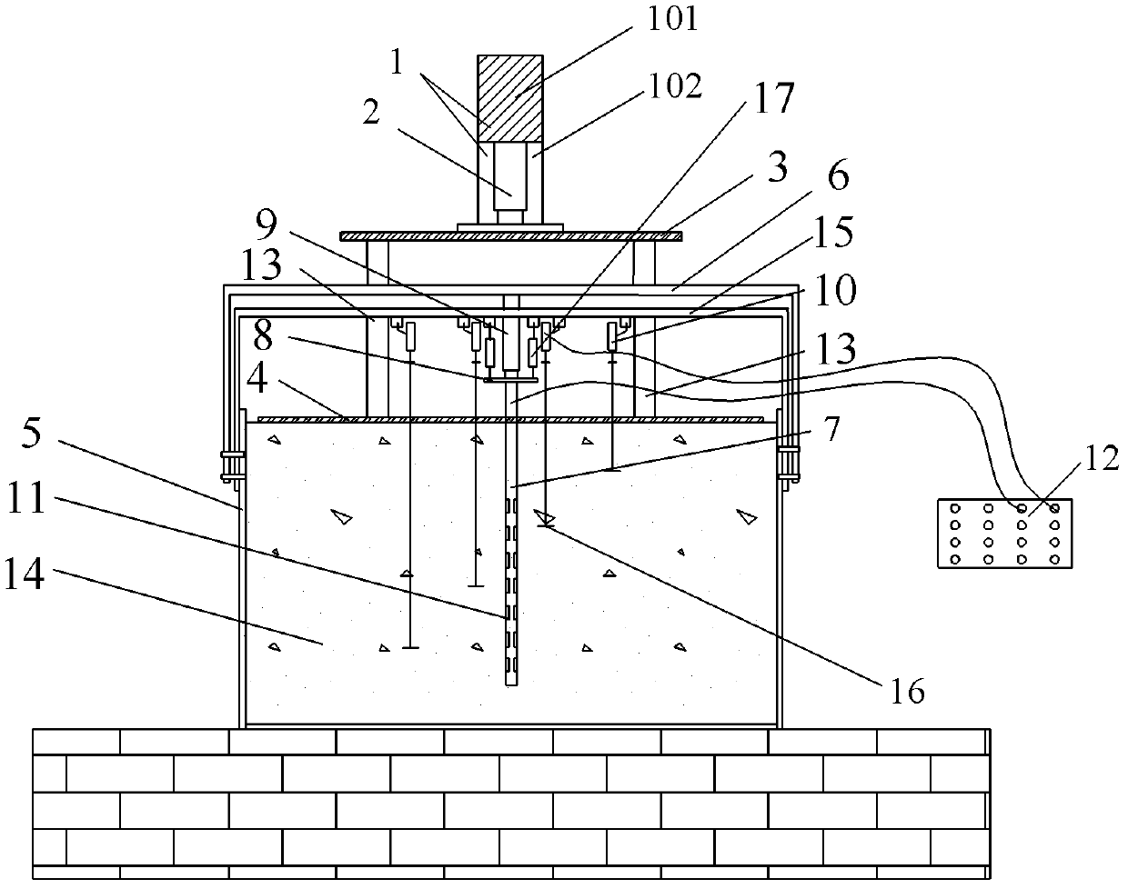
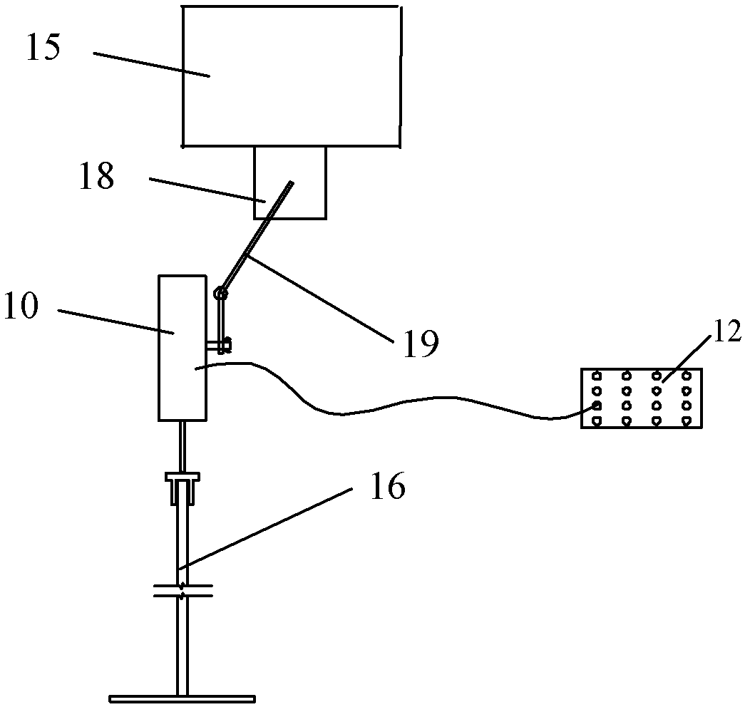
[0023] Such as Figure 1 to Figure 4 As shown, a measuring device for pile-soil negative friction resistance of the present invention includes a first reaction force device 1 containing a first top beam 101, an upper jack 2, an upper load plate 3, a lower load plate 4, and a soil body 14 of the test box 5, the second counter force device 6 containing the second top beam, the model pile 7, the bearing plate 8, the lower jack 9, the first displacement sensor 10, the strain gauge 11, the strain acquisition instrument 12, the balance beam 15. Settlement mark 16 and second displacement sensor 17. The first reaction force device 1 , the second reaction force device 6 and the strain collector 12 are located outside the test box 5 . The lower load plate 4 is located on the upper surface of the soil body 14 in the test box 5 . The lower load plate...


PUM


Abstract

The invention discloses a device for measuring negative skin friction of pile soil. The device comprises a first counter-force device, an upper jack, an upper loading plate, a lower loading plate, a test box body, a second counter-force device, a model pile, a pile cap, a lower jack, a first displacement sensor, a strain foil, a strain acquisition instrument, a balance beam, a subsidence mark and a second displacement sensor, wherein the lower loading plate is located on an upper surface of a soil body of the test box body; the top end of the model pile penetrates out of a through hole of the lower loading plate; the pile cap is located above the model pile; the lower jack is fixedly arranged on the top face of the pile cap; the upper loading plate is located above the second counter-force device; the upper jack is fixedly arranged on the top face of the upper loading plate; the subsidence mark is located in the soil body of the test box body; the first displacement sensor is located on the top end of the subsidence mark; the second displacement sensor is located on the top face of the pile cap; and the strain foil is attached to the surface of the model pile and is connected with the strain acquisition instrument. According to the measuring device, the jacks are utilized to load the soil body and the model pipe, so that a loading value is obtained, and the accuracy of negative skin friction measurement is ensured.

Description

[0001] technical field [0002] The invention relates to a device for measuring the properties of pile-containing soil, in particular to a device for measuring the negative friction resistance of pile-soil. [0003] Background technique [0004] At present, the problem of soil loading has not been well solved in the domestic and foreign pile foundation negative friction resistance laboratory tests. Existing studies mostly use high-pressure air or sand loading, but both methods have obvious defects. For example, judging from several cases of negative friction resistance tests using high-pressure air to load soil, although a large soil loading value (>100kPa) can be achieved, it needs to be carried out in a sealed container, except for the cost of test equipment. Outside the Philippines, due to the limited container space, it is impossible to carry out pile top loading and erection of related testing instruments. Therefore, the test is mostly limited to the study of the ...

Claims


Application Information

Patent Timeline
Patent Type & Authority Applications(China)
IPC IPC(8): G01L5/00
Inventor 戴国亮黄挺龚维明刘立基
Owner SOUTHEAST UNIV
Why Eureka
Try Eureka