Microparticle detection apparatus

A technology for detecting equipment and particles, which can be used in measuring devices, particle suspension analysis, scattering characteristic measurement, etc., and can solve the problems of reduced scattered light intensity and no significant increase in scattered light SNR.

Inactive Publication Date: 2012-07-25
SAMSUNG ELECTRONICS CO LTD +1
View PDF4 Cites 9 Cited by
  • Summary
  • Abstract
  • Description
  • Claims
  • Application Information

AI Technical Summary

Problems solved by technology

However, while the direct light may be attenuated, the intensity of the detected scattered light is also reduced and, as a result, does not significantly improve the SNR of scattered light detection

Method used


Image

  • Microparticle detection apparatus
  • Microparticle detection apparatus
  • Microparticle detection apparatus

Examples


Embodiment Construction

[0058] Reference will now be made in detail to exemplary embodiments of the invention, examples of which are illustrated in the accompanying drawings, wherein like reference numerals refer to like elements throughout.

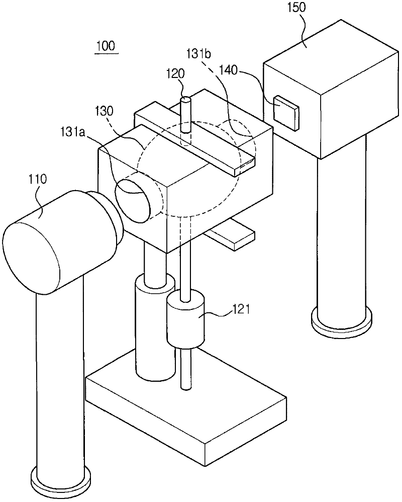
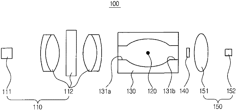
[0059] figure 2 shows a particle detection device 100 according to an embodiment of the present invention, image 3 is a cross-sectional view of the particle detection device 100 .

[0060] refer to figure 2 and image 3 , the particle detection apparatus 100 includes a light source unit 110 , an introduction unit 120 , an optical chamber 130 , a beam blocking unit 140 and a detection optical system 150 .

[0061] The light source unit 110 that irradiates light to sample particles includes an optical element 111 that emits light and a converging optical system 112 that condenses the light emitted from the optical element 111 .

[0062] The optical element 111 may include a laser diode (LD) (not shown) or a light emitting diode (LED) (not shown).

[0063]...


PUM


Abstract

A microparticle detection apparatus is provided. The microparticle detection apparatus includes a light emitting optical element, a converging optical system disposed in an advancing direction of light emitted from the optical element to converge the light, a particle path located in an advancing direction of the light having passed through the converging optical system so that the particle path intersects the light, a beam blocking unit to block direct light having passed through the particle path, a condensing lens disposed at the rear of the beam blocking unit, and a detector disposed at the rear of the condensing lens to detect light scattered by particles. A focal point of light formed by the optical element and the converging optical system may be located at the rear of the particle path. A focal point of light irradiated to the particles may be different from the introduction position of the particles.

Description

technical field [0001] Embodiments discussed herein relate to a particle detection device for optically detecting particles floating in the air. Background technique [0002] In recent years, attention to atmospheric safety has increased. Accordingly, particle detection technology is being developed for the public to easily monitor the state of the atmosphere in real time. [0003] Objects to be detected (for example, fine particles) having a size of 0.1 to 1 μm can be detected using a method of detecting scattering of light caused by irradiating light to an aerosol-phase sample. [0004] Scattering by particles is in the range of Mie scattering. The intensity of scattered light in the Mie scattering range can have as figure 1 The distribution shown in . [0005] Such as figure 1 Scattered light (dotted line) may have the highest distribution along substantially the same direction in which light (solid line) impinges on the particle, as shown in . [0006] Therefore, s...

Claims


Application Information

Patent Timeline
Patent Type & Authority Applications(China)
IPC IPC(8): G01N21/49G01N21/15
CPCG01N2015/035G01N15/06G01N21/21G01N21/64G01N21/53G01N2015/0693
Inventor 权俊亨尹斗燮卢禧烈金秀铉柳成润权元植李侠
Owner SAMSUNG ELECTRONICS CO LTD
Why Eureka
Try Eureka