Parallel operation line failure detection device and system
A fault detection and fault detection point technology, applied in the direction of measuring devices, measuring electricity, measuring electrical variables, etc., can solve problems such as the inability to quickly and accurately locate parallel lines, and achieve the effect of restoring normal operation and eliminating faults
- Summary
- Abstract
- Description
- Claims
- Application Information
AI Technical Summary
Problems solved by technology
Method used
Image

Examples
Embodiment 1
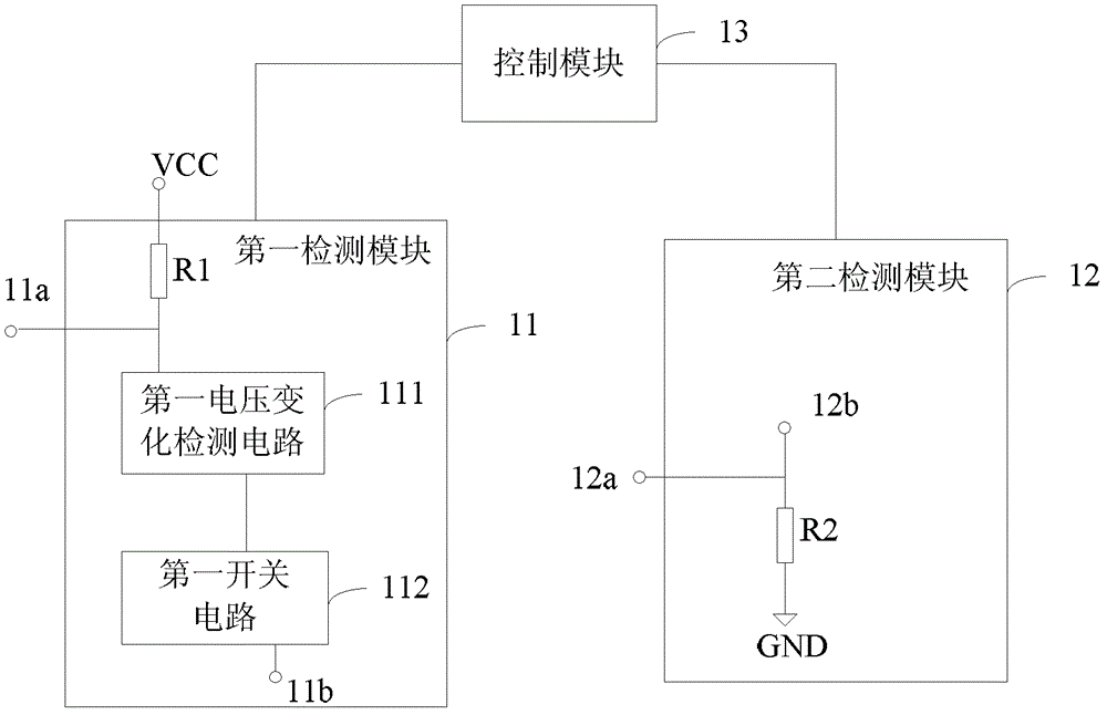
[0028] like figure 2 As shown, the embodiment of the present invention provides a parallel line fault detection device, which includes: a first detection module 11 , a second detection module 12 and a control module 13 . Specifically, the first detection module 11 is connected to a first pin of the first port, and the second detection module 12 is connected to a second pin of the second port. figure 2 Among them, the point 11a represents the connection point between the first detection module 11 and the first pin, and the point 12a represents the connection point between the second detection module 12 and the second pin.
[0029]The first detection module 11 includes a first resistor R1 , a first voltage change detection circuit 111 , and a first switch circuit 112 . The first resistor R1 is connected in series between the first pin and the power supply VCC. The first voltage change detection circuit 111 is used for outputting a first switch control signal according to the...
Embodiment 2
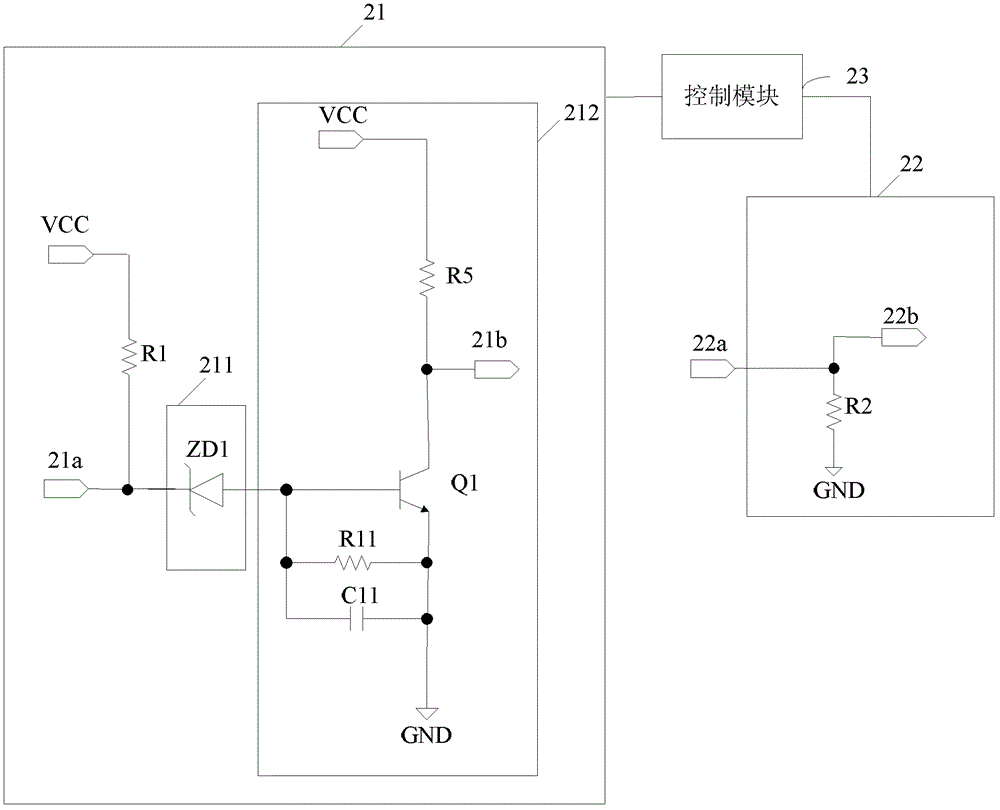
[0042] In this embodiment, the first voltage detection circuit using a Zener tube is used as an example to describe the parallel line fault detection device according to the embodiment of the present invention in detail. like image 3 As shown, this embodiment provides a parallel line fault detection device, which includes: a first detection module 21 , a second detection module 22 and a control module 23 . image 3 Among them, the point 21a represents the connection point between the first detection module 21 and the first pin, and the point 22a represents the connection point between the second detection module 22 and the second pin.
[0043] The first detection module 21 includes a first resistor R1 , a first voltage change detection circuit 211 , and a first switch circuit 212 . The first resistor R1 is connected in series between the first pin and the power supply VCC. The first voltage change detection circuit 211 is used to output the first switch control signal accor...
Embodiment 3
[0056] like Figure 4 As shown, this embodiment provides a parallel line fault detection device, the first detection module 21 and control module 23 of the device are the same as the parallel line fault detection device in Embodiment 2, but the second detection module 32 is the same as the implementation The second detection module 22 in Example 2 is different. Specifically, the difference is that the second detection module 32 of the device of this embodiment further includes a second switch circuit 321, the input end of the second switch circuit 321 is connected to the second pin, and the output end of the second switch circuit 321 A second fault detection point 32b is provided. The second switch circuit 321 is used to control the level state of the second fault detection point 32b according to the voltage change of the second pin.
[0057] Specifically, the second switch circuit 321 includes a second transistor Q2, the base of the second transistor Q2 is connected to the ...
PUM
 Abstract
Description
Claims
Application Information
 - R&D
- Intellectual Property
- Life Sciences
- Materials
- Tech Scout
- Unparalleled Data Quality
- Higher Quality Content
- 60% Fewer Hallucinations
Browse by: Latest US Patents, China's latest patents, Technical Efficacy Thesaurus, Application Domain, Technology Topic, Popular Technical Reports.
© 2025 PatSnap. All rights reserved.Legal|Privacy policy|Modern Slavery Act Transparency Statement|Sitemap|About US| Contact US: help@patsnap.com