Solid-state battery
A technology of solid batteries and solid electrolytes, applied in solid electrolytes, lithium batteries, battery electrodes, etc., can solve problems such as electrolyte leakage
- Summary
- Abstract
- Description
- Claims
- Application Information
AI Technical Summary
Problems solved by technology
Method used
Image

Examples
Embodiment approach 1
[0063] (Embodiment 1-a)
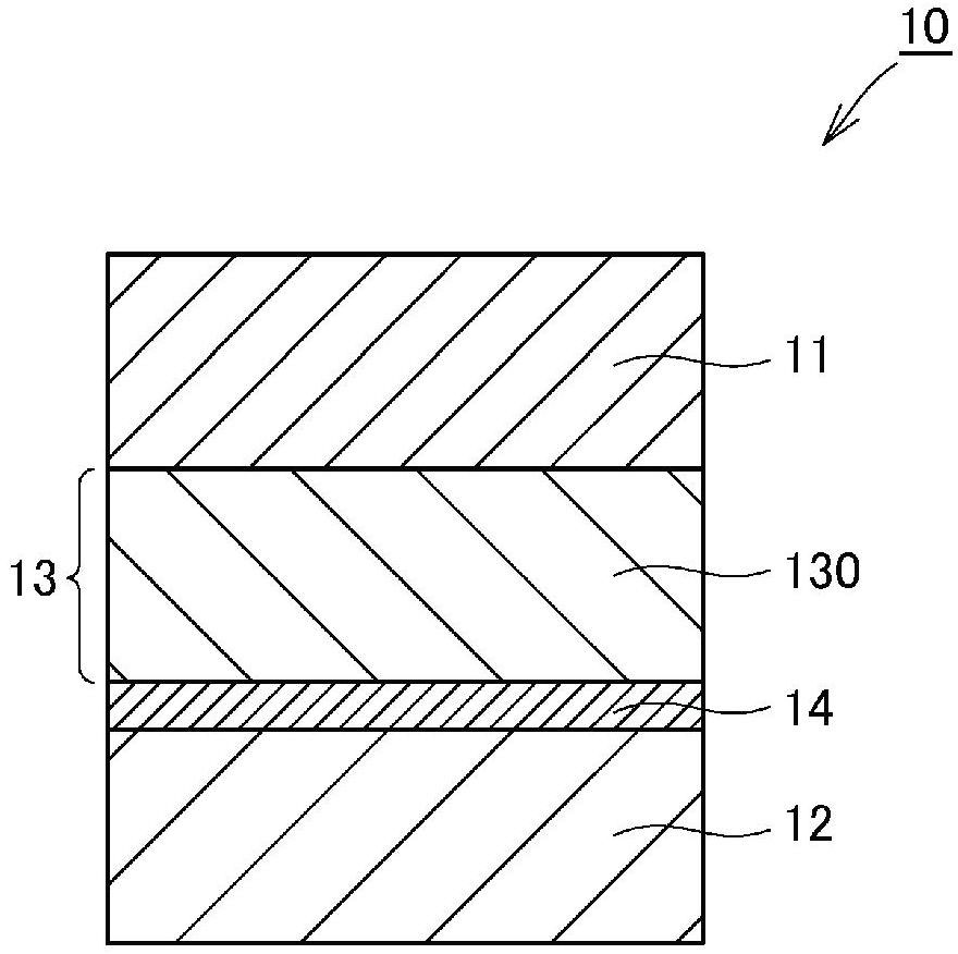
[0064] Such as figure 1 As shown, as a structural example (a) of the solid battery according to Embodiment 1 of the present invention, the solid battery 10 includes a positive electrode layer 11 , a negative electrode layer 12 , and a solid electrolyte layer 13 arranged between the positive electrode layer 11 and the negative electrode layer 12 . LiZr 2 (PO 4 ) 3 Containing layer 14 is provided between negative electrode layer 12 and solid electrolyte layer 13 . Solid electrolyte layer 13 is formed of first solid electrolyte layer 130 . Such as Figure 5 As shown, the first solid electrolyte layer 130 is composed of many solid electrolyte particles 15 . Positive electrode layer 11 or negative electrode layer 12 can be as Figure 7 As shown, it is composed of many electrode active material particles 16, and it can also be as Figure 8 As shown, it consists of a mixture of many solid electrolyte particles 15 and electrode active material particl...
Embodiment approach 1
[0065] (Embodiment 1-b)
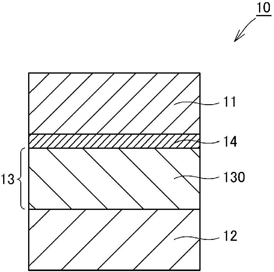
[0066] Such as figure 2 As shown, as a structural example (b) of the solid battery according to Embodiment 1 of the present invention, the solid battery 10 includes a positive electrode layer 11 , a negative electrode layer 12 , and a solid electrolyte layer 13 arranged between the positive electrode layer 11 and the negative electrode layer 12 . LiZr 2 (PO 4 ) 3 Containing layer 14 is provided between positive electrode layer 11 and solid electrolyte layer 13 . Solid electrolyte layer 13 is formed of first solid electrolyte layer 130 . Such as Figure 5 As shown, the first solid electrolyte layer 130 is composed of many solid electrolyte particles 15 . Positive electrode layer 11 or negative electrode layer 12 can be as Figure 7 As shown, it is composed of many electrode active material particles 16, and it can also be as Figure 8 As shown, it consists of a mixture of many solid electrolyte particles 15 and electrode active material partic...
Embodiment approach 1
[0067] (Embodiment 1-c)
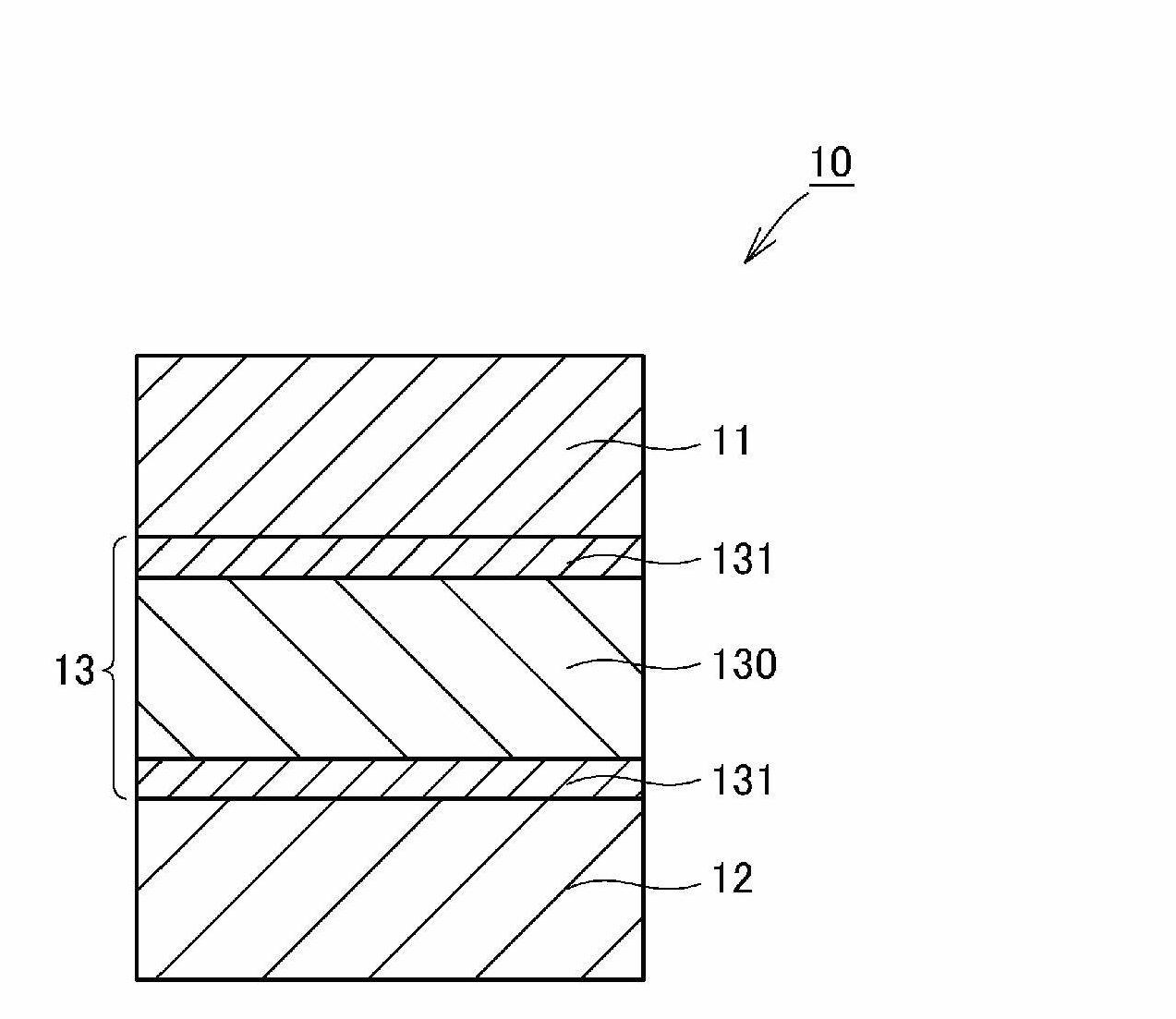
[0068] Such as image 3 As shown, as a structural example (c) of the solid battery according to Embodiment 1 of the present invention, the solid battery 10 includes a positive electrode layer 11 , a negative electrode layer 12 , and a solid electrolyte layer 13 arranged between the positive electrode layer 11 and the negative electrode layer 12 . The solid electrolyte layer 13 includes a first solid electrolyte layer 130 and two second solid electrolyte layers 131 disposed on both sides of the first solid electrolyte layer 130 . In other words, the second solid electrolyte layer 131 is disposed between at least one of the positive electrode layer 11 and the negative electrode layer 12 and the first solid electrolyte layer 130 . Such as Figure 5As shown, the first solid electrolyte layer 130 is composed of many solid electrolyte particles 15 . Such as Figure 6 As shown, the second solid electrolyte layer 131 is made of many LiZr 2 (PO 4 ) 3 It...
PUM
 Abstract
Description
Claims
Application Information
 - R&D
- Intellectual Property
- Life Sciences
- Materials
- Tech Scout
- Unparalleled Data Quality
- Higher Quality Content
- 60% Fewer Hallucinations
Browse by: Latest US Patents, China's latest patents, Technical Efficacy Thesaurus, Application Domain, Technology Topic, Popular Technical Reports.
© 2025 PatSnap. All rights reserved.Legal|Privacy policy|Modern Slavery Act Transparency Statement|Sitemap|About US| Contact US: help@patsnap.com