Laparoscope operating forceps capable of allowing bending angle of forceps head to be locked

A bending angle and laparoscopic technology, applied in the field of surgical forceps, can solve problems such as difficult disassembly and cleaning, labor-intensive assembly, complex structure, etc., and achieve the effects of saving resources, reducing carpal tunnel pressure, and reducing production costs

CN102614006AInactive Publication Date: 2012-08-01涂名超
9 Cites 46 Cited by

Patent Information

Authority / Receiving Office
CN · China
Patent Type
Applications(China)
Current Assignee / Owner
Publication Date
2012-08-01
Estimated Expiration
Not applicable · inactive patent

Smart Images

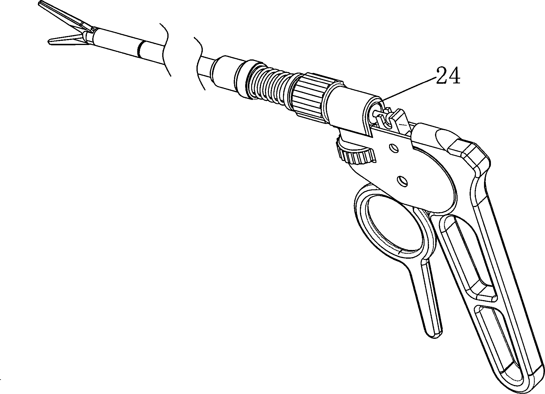
  • Figure 1
    Figure 1
  • Figure 2
    Figure 2
  • Figure 3
    Figure 3
Patent Text Reader

Abstract

The invention discloses a pair of laparoscope operating forceps capable of allowing locking the bending angle of a forceps head to be locked. The laparoscope operating forceps comprise a handheld part, a forceps nose, the forceps head and a control structure, wherein the handheld part comprises a drive toothed plate, a driven toothed piece and a handheld handle; the control structure is fixed on the handheld handle; the control structure is connected with the forceps head; the forceps head is connected with the forceps nose; a semi-circular part is formed at the front end of a core sleeve and is provided with convex teeth; two semi-circles are matched with each other; and the concave teeth are matched with the convex teeth. All the parts of the forceps are connected through tip shafts and hole buckles and are fixed through pipe sleeves, so that the laparoscope operating forceps is convenient to produce and assemble and the cost is reduced; the wrist channel pressure is reduced, fatigue is eliminated and the accuracy of the surgery is improved; the forceps rod head can serve as a disposable product; and the forceps rod head can also be disassembled into parts, and the parts are combined for use for many times after being cleaned and disinfected, so resources are saved.
Need to check novelty before this filing date? Find Prior Art

Description

technical field

[0001] The invention relates to the field of surgical forceps, in particular to a laparoscopic surgical forceps. Background technique

[0002] The laparoscopic surgical forceps disclosed in the prior art are all designed with a straight head and no bendable angle, such as: Chinese patent numbers 200420022085.5, 200910096133.2, 200720191453.2, 200920115267.X. In many laparoscopic operations, due to deep abdominal lesions, its position is narrow, and the head of the general straight extension forceps cannot be bent, so it is entirely up to the doctor to twist the wrist joint to adjust and control the surgical forceps to perform the operation process. The traditional way of holding the pliers handle tends to make the wrist joint deviate, which will reduce the movement and distortion of the forearm cross-wrist muscles, thereby increasing the pressure on the carpal tunnel and causing wrist fatigue.

[0003] The mutual connection mode of the movable joints of the ...

Examples

Embodiment Construction

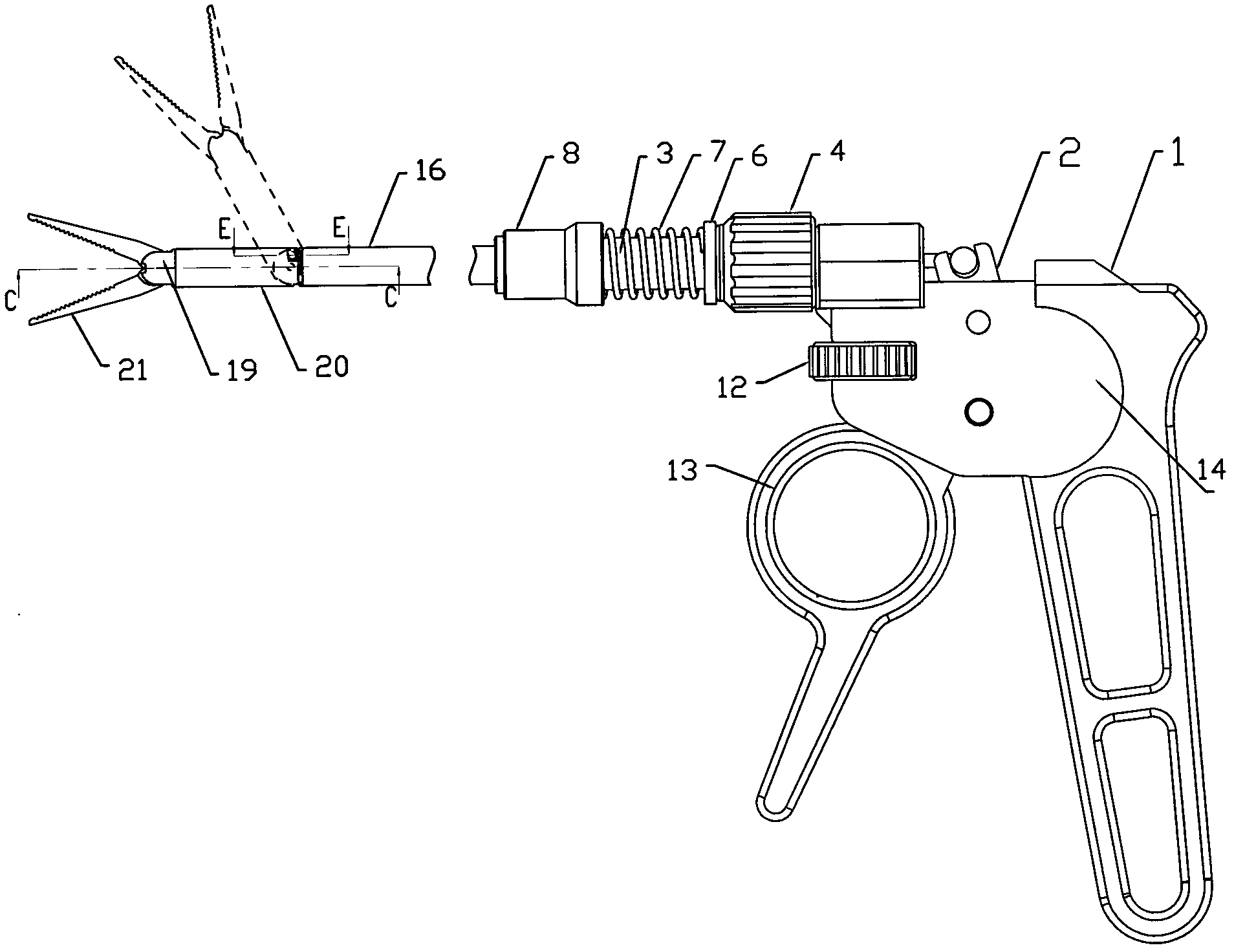
[0035] The present invention will be further described below in conjunction with the accompanying drawings and embodiments.

[0036] Such as Figure 1-18 Shown: the laparoscopic surgical forceps that can lock the bending angle of the pliers head, including: the hand-held part, the pliers mouth, the pliers head, and the control structure. The control structure includes: core sleeve 3, internal thread knob 4, anti-rotation screw 5, fixed sleeve 6, spring 7, telescopic sleeve 8, elbow active pull rod 9, pliers mouth active pull rod 10, screw lock 11, fixed knob 12 The right end of the core sleeve 3 is located in the ring sleeve 24 of the handle 1, and the left end is connected to the pliers head; a groove 3c is arranged in the core sleeve, and the left end of the active pull rod 10 of the pliers mouth has a spherical hole 10a, and the right end has a ball head 10b The other end of the ball head 10b is fixed in the fork groove of the driven gear 2, the spherical hole 10a is locat...