Centrifugal deduster

A technology of dust collector and centrifugal cylinder, which is applied in the direction of separation method, dispersed particle separation, chemical instrument and method, etc. It can solve the problems of high temperature chemical corrosion resistance, many faults, low dust removal efficiency, etc., and achieve long service life and low operating cost. low dust removal efficiency

Inactive Publication Date: 2012-08-01
黄云生
View PDF9 Cites 4 Cited by
  • Summary
  • Abstract
  • Description
  • Claims
  • Application Information

AI Technical Summary

Problems solved by technology

[0003] In order to overcome the problems of low dust removal efficiency, many faults, high temperature resistance and chemical corrosion existing in various dust removal technologies in the prior art, the present invention provides a centrifugal dust collector, which has a simple and compact structure, high dust removal efficiency, Stable operation and strong reliability

Method used


Image

  • Centrifugal deduster
  • Centrifugal deduster
  • Centrifugal deduster

Examples


Embodiment Construction

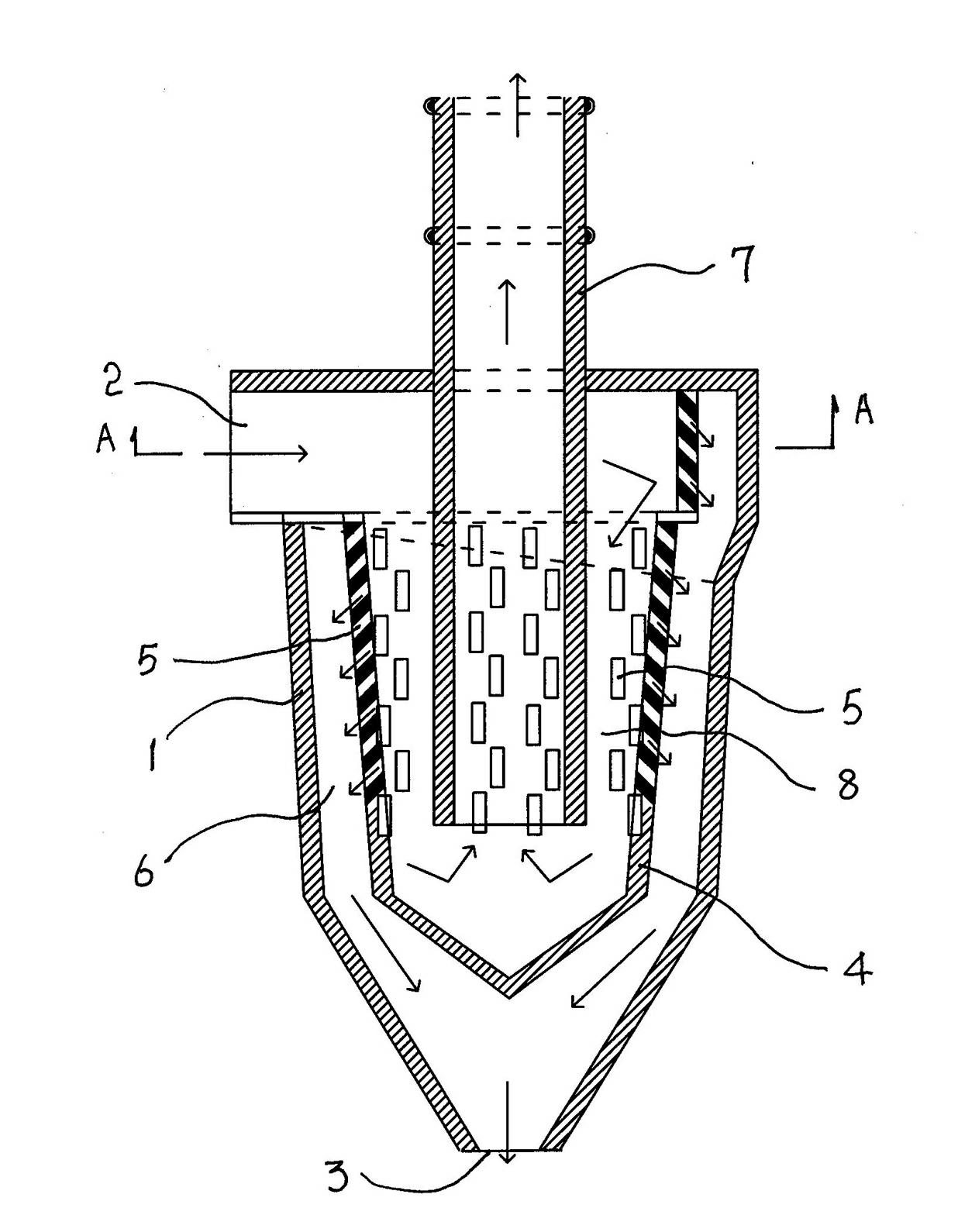
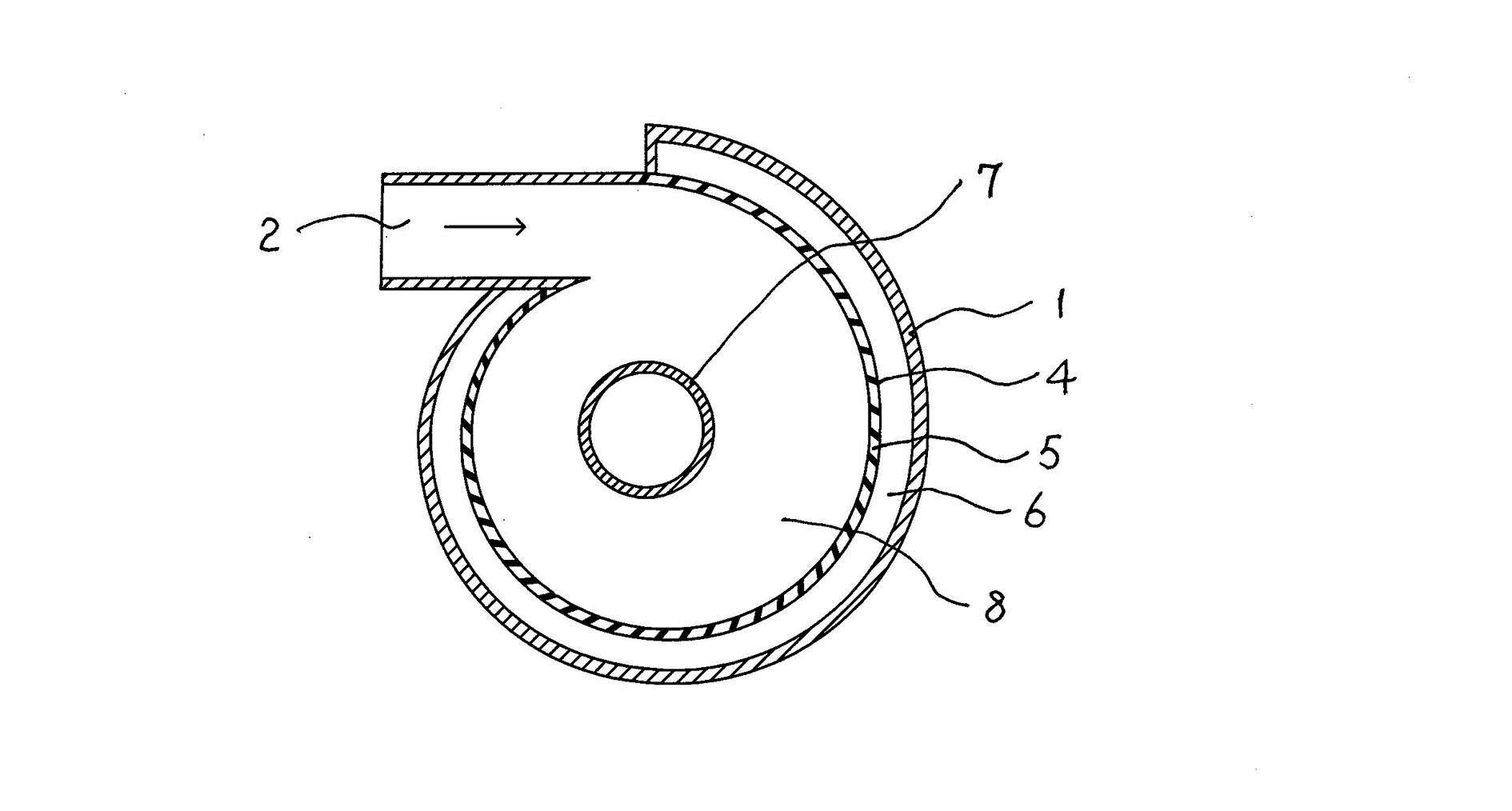
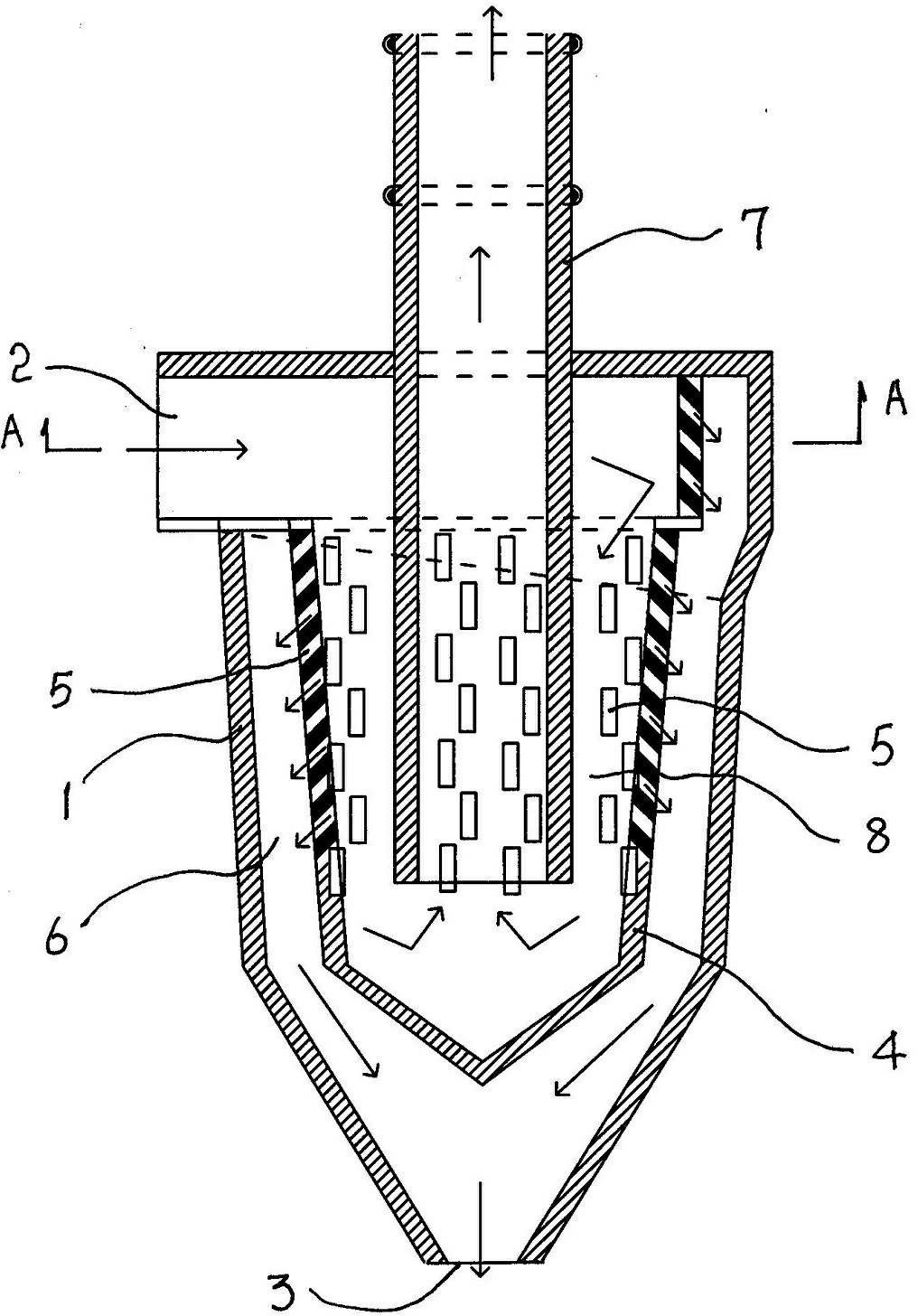
[0012] As shown in the figure, the present invention includes a body 1, which is conical, and the lower part of the body 1 shrinks radially. The upper side of the body 1 is provided with an air inlet 2, and the lower end of the body 1 is provided with a dust outlet 3, and a centrifugal cylinder 4 with a closed bottom is fixed in the body 1, and the closed bottom of the centrifugal cylinder 4 shrinks in a conical shape. The air inlet 2 is connected to the centrifugal cylinder 4 in a tangential direction, and the dust escape port 5 is evenly distributed on the side wall of the centrifugal cylinder 4, and the dust escape port 5 can be evenly distributed on the side wall of the centrifugal cylinder 4 in a tangential direction, further enhancing the centrifugal effect. The dust falling channel 6 is formed between the side wall of the centrifugal cylinder 4 and the shell 1, the upper end of the body 1 is fixed with an exhaust pipe 7, and the exhaust pipe 7 extends into the centrifuga...


PUM


Abstract

The invention relates to a centrifugal deduster, which comprises a deduster body, wherein an air inlet is formed on the lateral part of the upper end of the deduster body; a dustfall opening is formed at the lower end of the deduster body; a centrifugal cylinder of which the bottom is closed is fixed in the deduster body; the air inlet is connected to the centrifugal cylinder in the tangential direction; dust removal openings are distributed on the side wall of the centrifugal cylinder uniformly in the tangential direction; a dustfall channel is formed between the side wall of the centrifugal cylinder and a shell; an exhaust pipe is fixed to the upper end of the deduster body and extends into the centrifugal cylinder; and a centrifugal dedusting channel is formed between the exhaust pipe and the centrifugal cylinder. By the centrifugal deduster, the defects of low dedusting efficiency, multiple faults, incapability of resisting high temperature and chemical corrosion in various dedusting technologies in the prior art are overcome; and due to the adoption of the specific design, the centrifugal deduster has the advantages of simple and compact structure, high dedusting efficiency, long service life, low fault rate, wide application range, low running cost and small air flow resistance.

Description

technical field [0001] The invention relates to a centrifugal dust collector. Background technique [0002] A large amount of dust is volatilized in industrial development. The dust removal technologies currently used include bag pulse dust removal, cyclone dust removal, electrostatic dust removal, specific gravity sedimentation dust removal, water mist dust removal, and swirl plate dust removal. There are various defects, the most prominent ones are low dust removal efficiency, many faults, and inability to withstand high temperature and chemical corrosion. Contents of the invention [0003] In order to overcome the problems of low dust removal efficiency, many faults, high temperature resistance and chemical corrosion existing in various dust removal technologies in the prior art, the present invention provides a centrifugal dust collector, which has a simple and compact structure, high dust removal efficiency, Stable operation and strong reliability. [0004] The tech...

Claims


Application Information

Patent Timeline
Patent Type & Authority Applications(China)
IPC IPC(8): B01D45/16
Inventor 黄云生
Owner 黄云生
Why Eureka
Try Eureka