Supercharge Your Innovation With Domain-Expert AI Agents!

Cutting machine and cutting blade replacement method

A cutting blade and cutting machine technology, applied in metal processing and other directions, can solve problems such as unusability

Active Publication Date: 2016-09-07
PLUS CORP
View PDF4 Cites 0 Cited by
  • Summary
  • Abstract
  • Description
  • Claims
  • Application Information

AI Technical Summary

Problems solved by technology

Therefore, if there is not enough space for arranging support members etc. around the cutting blade, there will be a problem that it cannot be used.

Method used


Image

  • Cutting machine and cutting blade replacement method
  • Cutting machine and cutting blade replacement method
  • Cutting machine and cutting blade replacement method

Examples


Embodiment Construction

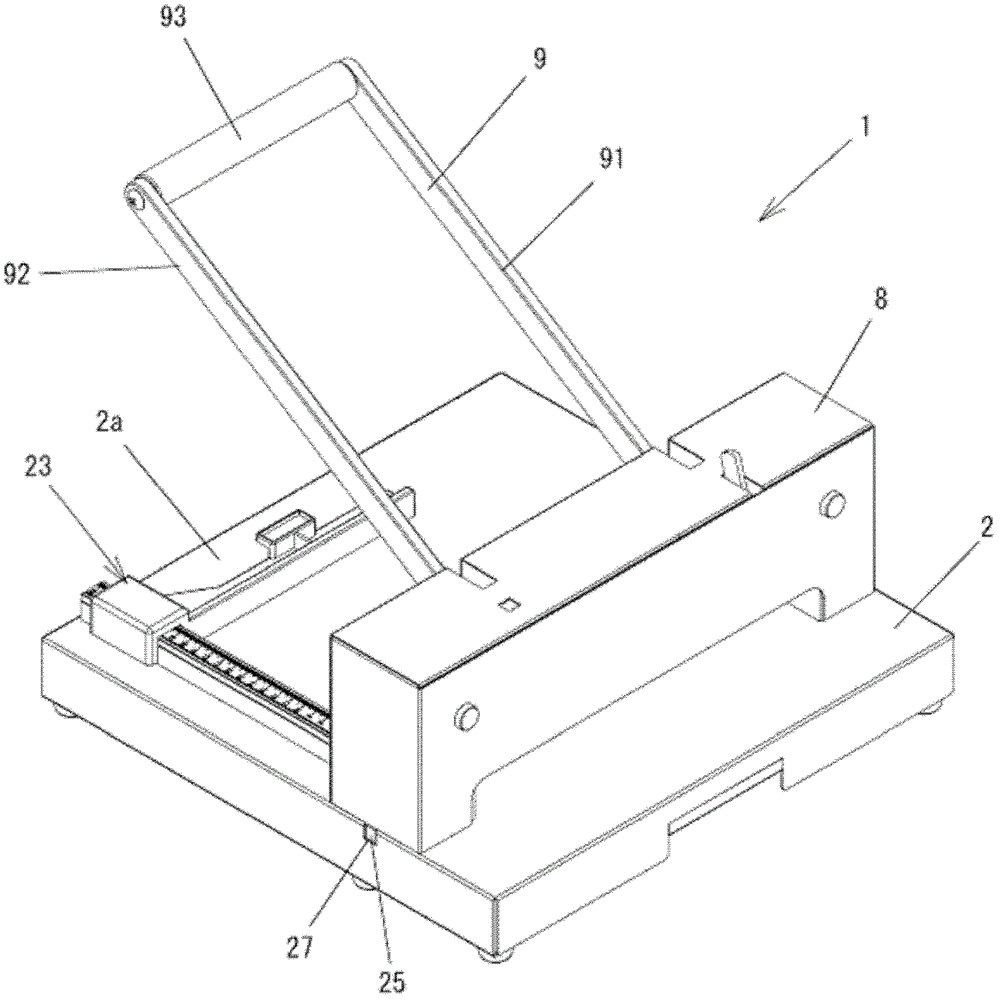
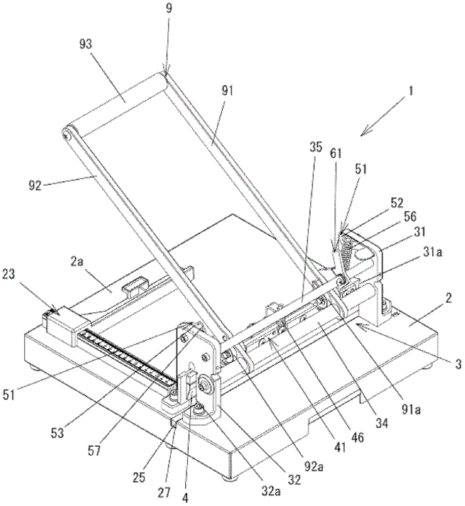
[0057] Embodiments of the present invention will be described in detail below with reference to the accompanying drawings. The present invention relates to a method for easily and safely replacing a cutting blade in a cutting machine for cutting paper or the like. First, after explaining the structure of the cutting machine in this embodiment, the cutting blade case used for replacing the cutting blade and the replacement method will be described. figure 1 It is a rear perspective view of the cutting machine 1 according to the embodiment of the present invention, figure 2 For taking off the back perspective view under the state of cutting machine main body casing 8, image 3 It is an exploded perspective view with the main casing 8 removed. In addition, in the following description, the direction where the handle is located is upward, the direction where the base is located is downward, the direction where the base body casing 8 is located is the rear, and the direction opp...


PUM


Abstract

[Problem] The present invention provides a cutting machine in which cutting blades can be safely replaced. [Solution] A cutting machine equipped with a cutting blade casing (7), wherein the cutting blade casing (7) is formed into a tapered cutting blade (4) with a cutting edge portion below it by pressing The cutting machine for cutting the paper placed between the blade supporting member and the cutting blade on the blade supporting member placement groove of the base is used when the cutting blade (4) is replaced, and has a rear plate (71) extending in the left and right direction and a rear plate (71) located on the In front of the rear plate (71), a front plate (72) extending in the left-right direction, between the rear plate (71) and the front plate (72) there is a storage space (75) for accommodating the blade portion of the cutting blade (4) , by forming the length in the front-rear direction to be shorter than the length in the front-rear direction of the blade support member placement groove, it can be inserted into the blade support member placement groove when replacing the cutting blade (4).

Description

technical field [0001] The invention relates to a cutting machine, a cutting blade casing used when the cutting machine replaces a cutting blade, and a cutting blade replacement method using the cutting blade casing to replace the cutting blade. technical background [0002] There is a tool called a cutter that cuts paper, etc. in a straight line. This cutting machine is provided with a cutting blade, but after the cutting blade is used continuously, due to the loosening and wearing of the blade, the cutting blade edge becomes blunt and no longer sharp, so it needs to be properly replaced. When the cutting blade is replaced, the edge portion of the cutting blade is exposed, which is often accompanied by danger. Therefore, a method that can safely replace the cutting blade is required. For example, in Japanese Patent Laying-Open No. 11-267919 (Patent Document 1), in order to safely replace the cutting blade, it is proposed to install an L-shaped scabbard on the cutting blade...

Claims


Application Information

Patent Timeline
Patent Type & Authority Patents(China)
IPC IPC(8): B26D7/26B26D7/22
CPCB26D1/085B26D5/10B26D7/22B26D7/26
Inventor 小堺哲男添田修一细川祐一
Owner PLUS CORP
Features
  • R&D
  • Intellectual Property
  • Life Sciences
  • Materials
  • Tech Scout
  • Unparalleled Data Quality
  • Higher Quality Content
  • 60% Fewer Hallucinations
Learn More