Guide wheel device on numerical control multi-wire swinging cutting machine

A cutting machine and guide wheel technology, applied to fine working devices, working accessories, stone processing equipment, etc., can solve the problems of increasing broken wires, achieve the effects of improving actual life, reducing the probability of wire breaking, and extending life

Inactive Publication Date: 2012-08-01
无锡市协清机械制造有限公司
View PDF5 Cites 12 Cited by
  • Summary
  • Abstract
  • Description
  • Claims
  • Application Information

AI Technical Summary

Problems solved by technology

In addition, since the guide wheel device uses a bearing to run at high speed, the bearing will shake during operation, which increases the probability of broken wires

Method used


Image

  • Guide wheel device on numerical control multi-wire swinging cutting machine
  • Guide wheel device on numerical control multi-wire swinging cutting machine
  • Guide wheel device on numerical control multi-wire swinging cutting machine

Examples


Embodiment Construction

[0009] The present invention will be further described below in conjunction with specific drawings.

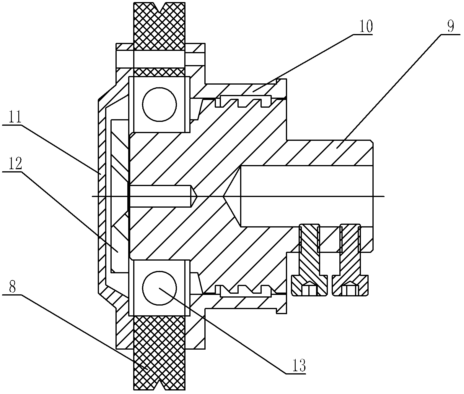
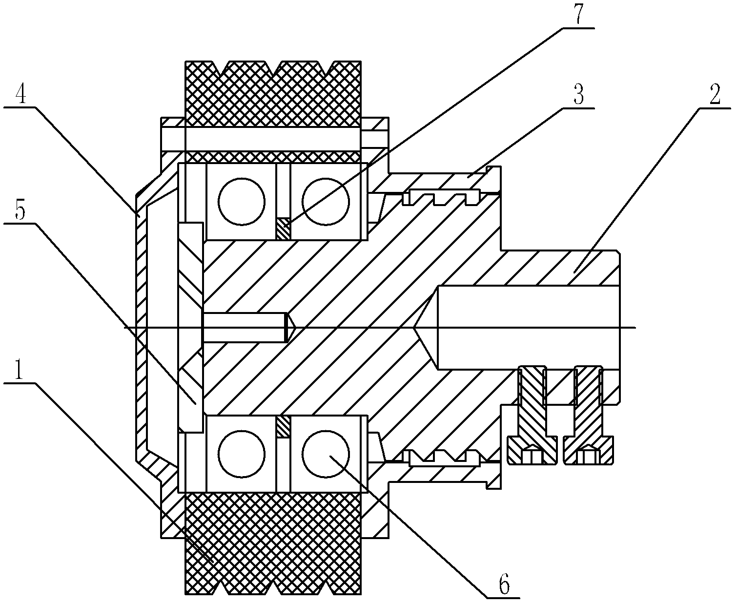
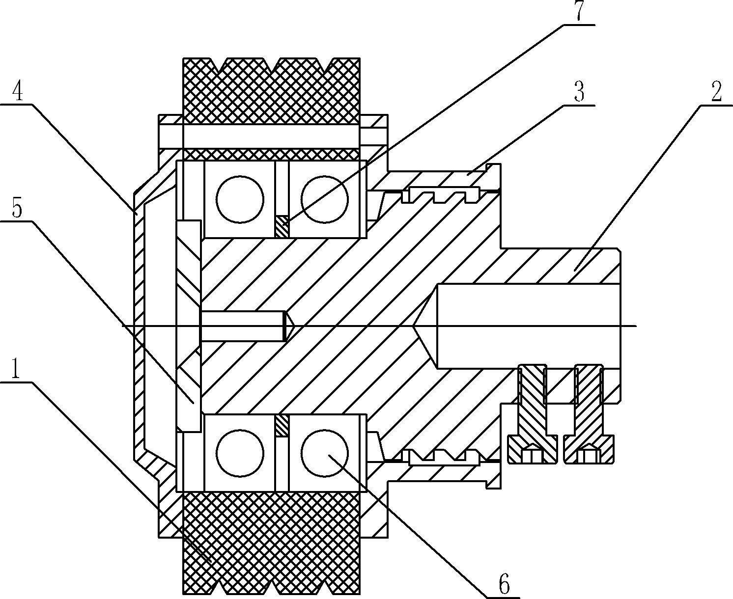
[0010] Such as figure 2 Shown: The guide wheel device used on the CNC multi-wire swing cutting machine includes a large guide wheel 1, a large wheel shaft 2, a rear gland 3, a front gland 4, a pressure pad 5, a bearing 6, and a spacer 7.

[0011] The present invention includes a large wheel shaft 2, on which a large guide wheel 1 is installed, and the large guide wheel 1 is installed on the large wheel shaft 2 through two pairs of bearings 6, and a spacer is arranged between the two pairs of bearings 6 7; Install the front gland 4 at the front end of the large guide wheel 1, set the pressure pad 5 between the front gland 4 and the large wheel shaft 2, and install the rear gland 3 at the rear end of the large guide wheel 1; The width of the large guide wheel 1 is wider than that of the prior art, and three grooves are provided on the outer peripheral surface of the large guid...


PUM


Abstract

The invention relates to a guide wheel device on a numerical control multi-wire swinging cutting machine, which comprises a large wheel shaft provided with a large guide wheel and is characterized in that the large guide wheel is arranged on the large wheel shaft through two pairs of bearings, a partition sleeve is arranged between the two pairs of bearings, a front gland is arranged at the front end of the large guide wheel, a pressing pad is arranged between the front gland and the large wheel shaft, and a back gland is arranged at the back end of the large guide wheel. The guide wheel of the guide wheel device on the numerical control multi-wire swinging cutting machine is widened, three grooves are arranged on the guide wheel, and simultaneously double-bearing supporting is adopted, so that practical service life of the guide wheel is prolonged and wire breaking probability is reduced. Compared with like products, the guide wheel device on the numerical control multi-wire swinging cutting machine has obvious advantages, service life is prolonged to be 600 hours, and wire breaking probability is greatly reduced.

Description

technical field [0001] The invention relates to a guide wheel device, in particular to a guide wheel device used on a CQ-28 numerical control multi-wire swing cutting machine. Background technique [0002] The current design of the guide wheel device is usually as follows figure 1 As shown, including wheel shaft 9, guide wheel 8 is installed on wheel shaft 9, and guide wheel 8 is installed on the wheel shaft 9 by a pair of bearings 13, and front gland 11 and rear gland 10 are installed respectively at the front and rear ends of guide wheel 8, in A pressure pad 12 is arranged between the front gland and the wheel shaft 9; the width of the guide wheel 8 is relatively small, and a groove is provided on the outer circumference of the guide wheel 8. The actual service life of the guide wheel of this structure is 200 hours, and the replacement of the guide wheel must be assisted by special tooling. The operation is difficult, and improper operation will cause disordered lines, w...

Claims


Application Information

Patent Timeline
IPC IPC(8): B28D7/00B28D5/04
Inventor 席洪清
Owner 无锡市协清机械制造有限公司
Why Eureka
Try Eureka