Safety antitheft device of electric vehicle

An anti-theft device, a technology for electric vehicles, applied in vehicle parts, transportation and packaging, vehicle accessories for anti-theft, etc., can solve problems such as poor adjustment of vibration sensor sensitivity, false alarms, and battery theft.

Inactive Publication Date: 2012-08-01
河南护航智能科技有限公司
View PDF4 Cites 6 Cited by
  • Summary
  • Abstract
  • Description
  • Claims
  • Application Information

AI Technical Summary

Problems solved by technology

[0002] Generally, the anti-theft function of electric vehicles is realized in the following way: the anti-theft circuit is connected to the electric vehicle battery of the electric vehicle through a switch, wherein the anti-theft circuit is composed of a DC / DC power conversion module, a vibration sensor, a control unit and an alarm horn. When the owner leaves, the switch is closed, and the anti-theft alarm starts to work. When someone moves or touches the electric vehicle, the vibration sensor outputs an electrical signal to the control unit, and the control unit controls the alarm horn to emit an alarm sound to achieve the effect of warning the anti-theft. However, such an anti-theft device has the following problems: 1, the anti-theft circuit switch needs to be manually controlled to close it, which is inconvenient, and sometimes there is a leakage of defense; 2, the sensitivity of the vibration sensor is not easy to adjust, and often false alarms; 3, The anti-theft circuit is exposed and easily damaged; 4. The anti-theft effect is not ideal
[0003] Therefore, even if the electric vehicle is equipped with an anti-theft device, the anti-theft effect that can be played is still very small, and the phenomenon that electric vehicles, especially electric vehicle batteries, are stolen is still not uncommon.

Method used


Image

  • Safety antitheft device of electric vehicle
  • Safety antitheft device of electric vehicle
  • Safety antitheft device of electric vehicle

Examples


Embodiment Construction

[0020] The technical solutions of the present invention will be described in further detail below through specific implementation methods.

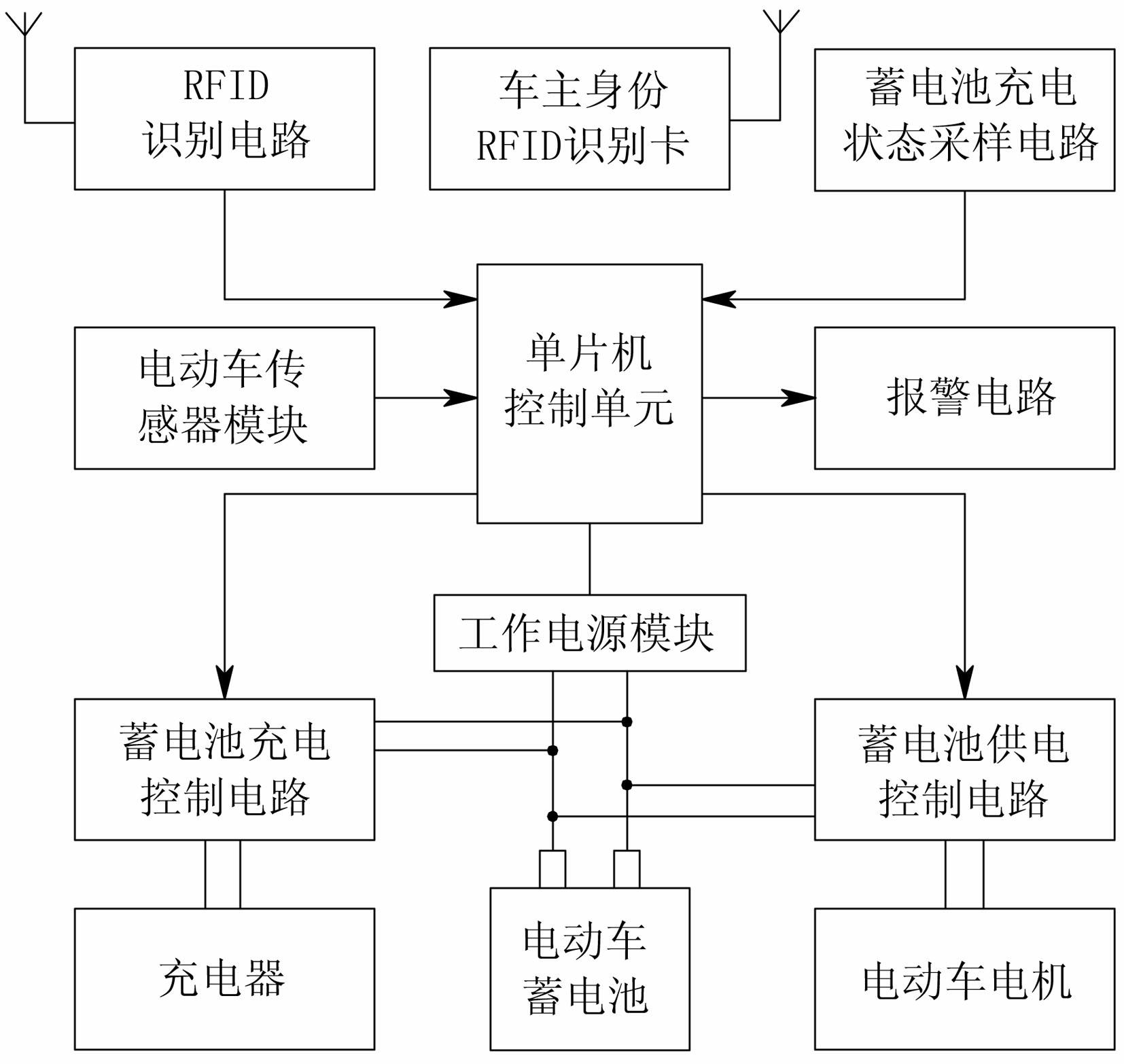
[0021] Such as figure 1 As shown, a safety anti-theft device for an electric vehicle includes a single-chip microcomputer control unit, an RFID communication unit, an electric vehicle sensor module, an alarm circuit, a battery power supply control circuit, a battery charging state sampling circuit, a battery charging control circuit, an electric vehicle battery and a working Power supply module; the single-chip microcomputer control unit includes a single-chip microcomputer chip U1 of model STC12C5608AD and peripheral circuits such as a crystal oscillator circuit and a reset circuit.

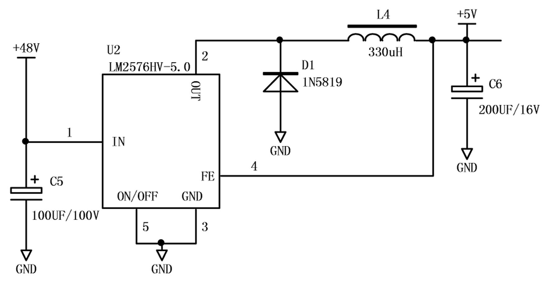
[0022] The working power supply module is mainly composed of a voltage conversion chip U2 and its peripheral circuits whose model is LM2576HV-5.0, such as figure 2 As shown, the 48V voltage of the battery of the electric vehicle is filtered by the capacit...


PUM


Abstract

The invention provides a safety antitheft device of an electric vehicle. The safety antitheft device comprises a single-chip microcomputer control unit, a radio-frequency identification (RFID) communication unit, an electric vehicle sensor module, an alarm circuit, an electric vehicle storage battery and a storage battery power supply control circuit. The RFID communication unit conducts heat beat communication with the single-chip microcomputer control unit to realize the automatic defense of the electric vehicle. The single-chip microcomputer control unit judges whether to control the on and off of the storage battery power supply control circuit or not according to the automatic defense state of the electric vehicle. The single-chip microcomputer control unit judges whether to control the alarm circuit to alarm or not according to electric vehicle vibration signals or movement signals acquired by the electric vehicle sensor module and the automatic defense state of the electric vehicle. By adopting an RFID technique, the defense and the defense canceling of the electric vehicle are automatically realized, the problem that people forget to set up defenses is avoided and the antitheft effect is reinforced.

Description

technical field [0001] The invention relates to an anti-theft device, in particular to an electric vehicle safety anti-theft device. Background technique [0002] Generally, the anti-theft function of electric vehicles is realized in the following way: the anti-theft circuit is connected to the electric vehicle battery of the electric vehicle through a switch, wherein the anti-theft circuit is composed of a DC / DC power conversion module, a vibration sensor, a control unit and an alarm horn. When the owner leaves, the switch is closed, and the anti-theft alarm starts to work. When someone moves or touches the electric vehicle, the vibration sensor outputs an electrical signal to the control unit, and the control unit controls the alarm horn to emit an alarm sound to achieve the effect of warning the anti-theft. However, such an anti-theft device has the following problems: 1, the anti-theft circuit switch needs to be manually controlled to close it, which is inconvenient, and...

Claims


Application Information

Patent Timeline
Patent Type & Authority Applications(China)
IPC IPC(8): B60R25/10B60R25/04
Inventor 曲保章
Owner 河南护航智能科技有限公司
Why Eureka
Try Eureka