Full-automatic heavy electronic door lock

An electronic door lock, fully automatic technology, used in non-mechanical transmission-operated locks, building locks, buildings, etc., can solve the problem of increasing the structure of the door lock, achieve the simplification of the door lock structure, simple and convenient operation, and reduce the transmission structure. Effect

Pending Publication Date: 2022-05-03
ZHONGSHAN ROYALWAND HARDWARE
View PDF0 Cites 0 Cited by
  • Summary
  • Abstract
  • Description
  • Claims
  • Application Information

AI Technical Summary

Problems solved by technology

[0002] Electronic door lock refers to a composite automatic lock with safety, convenience and advanced technology, which is different from traditional mechanical locks. In addition to the function of locking or unlocking mechanically through the key, it can also be used with the help of motor intelligence. Realize the locking and unlocking functions of fully automatic locks; most of the electronic door locks currently use a set of main bolts to lock the door body, and the existing unlocking fork assembly only needs to drive a set of bolts. It can meet the needs of locking and unlocking, but when some doors need to improve the safety factor, they usually use heavy-duty locks such as Overlord locks. The door locks of this part add two sets of auxiliary bolts on the basis of ordinary electronic door locks. Improve the stability of the lock, which leads to an increase in the structure of the door lock, so further improvements are required to the unlocking fork assembly in the door lock

Method used


Image

  • Full-automatic heavy electronic door lock
  • Full-automatic heavy electronic door lock
  • Full-automatic heavy electronic door lock

Examples


Embodiment Construction

[0030] The present invention will be further described below in conjunction with the accompanying drawings and embodiments.

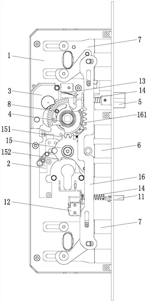
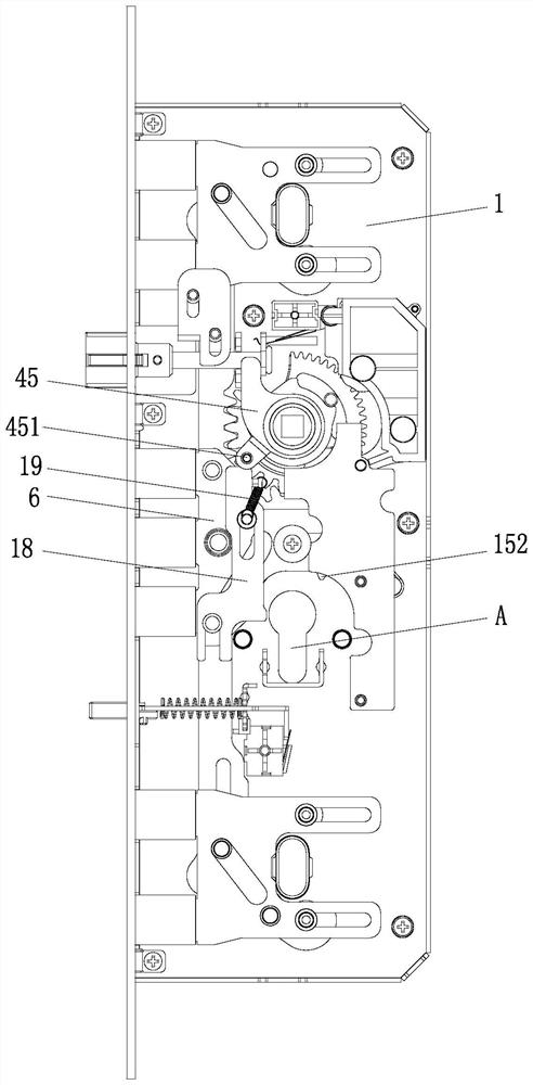
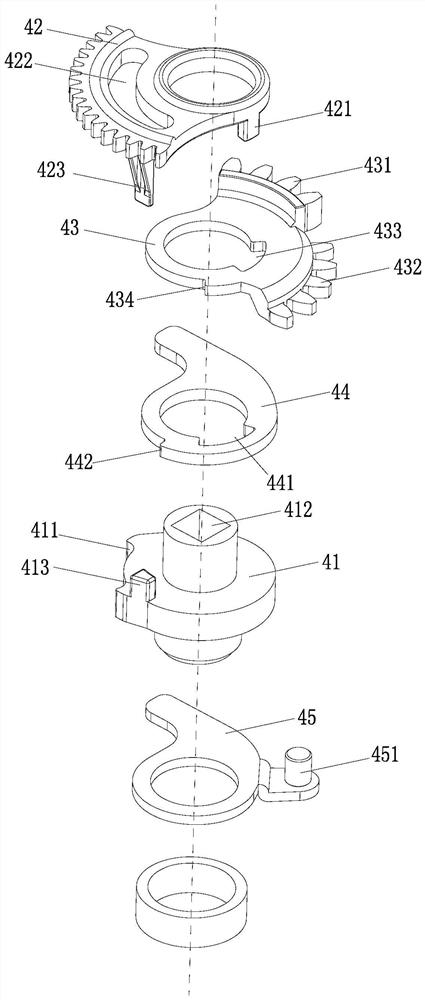
[0031] Such as Figure 1 to Figure 10 As shown, the fully automatic heavy-duty electronic door lock includes a housing 1, and the housing 1 is provided with an electric control board 2, a drive controller 3, an unlocking shift fork assembly 4, an oblique bolt 5, a main bolt assembly 6 and an auxiliary The deadbolt assembly 7, the drive controller 3 is electrically connected with the electric control board 2 and drives the main bolt assembly 6 and the auxiliary deadbolt assembly 7 to move through the unlocking shift fork assembly 4. The unlocking shift fork assembly 4 includes a dial 41 and Rotate the prime mover gear 42 that is arranged on the dial 41, the interlocking gear 43 and the front latch tongue shift fork 44, and the described prime mover gear 42 is respectively connected with the output end of the drive controller 3, the interlock gear 43 and ...


PUM


Abstract

The invention relates to a full-automatic heavy electronic door lock which comprises a shell, an electric control board, a driving controller, an unlocking shifting fork assembly, a latch bolt, a main spring bolt assembly and an auxiliary spring bolt assembly are arranged in the shell, and the driving controller is electrically connected with the electric control board and drives the main spring bolt assembly and the auxiliary spring bolt assembly to move through the unlocking shifting fork assembly. The unlocking shifting fork assembly comprises a shifting wheel, a driving gear, a linkage gear and a front latch bolt shifting fork, the driving gear, the linkage gear and the front latch bolt shifting fork are rotationally arranged on the shifting wheel, the driving gear is in transmission connection with the output end of the driving controller, the linkage gear and the front latch bolt shifting fork, and the front latch bolt shifting fork is in transmission connection with the latch bolt. The linkage gear is provided with a first tooth surface and a second tooth surface, the first tooth surface and the second tooth surface are in transmission connection with the auxiliary spring bolt assembly and the main spring bolt assembly respectively, according to the structure, the auxiliary spring bolt assembly and the main spring bolt assembly can be driven through the first tooth surface and the second tooth surface at different angles, the door lock structure is simplified, and operation is easy and convenient.

Description

technical field [0001] The invention relates to the field of intelligent door locks, in particular to a fully automatic heavy-duty electronic door lock. Background technique [0002] Electronic door lock refers to a composite automatic lock with safety, convenience and advanced technology, which is different from traditional mechanical locks. In addition to the function of locking or unlocking mechanically through the key, it can also be used with the help of motor intelligence. Realize the locking and unlocking functions of fully automatic locks; most of the electronic door locks currently use a set of main bolts to lock the door body, and the existing unlocking fork assembly only needs to drive a set of bolts. It can meet the needs of locking and unlocking, but when some doors need to improve the safety factor, they usually use heavy-duty locks such as Overlord locks. The door locks of this part add two sets of auxiliary bolts on the basis of ordinary electronic door locks...

Claims


Application Information

Patent Timeline
Patent Type & Authority Applications(China)
IPC IPC(8): E05B63/14E05B47/00E05B17/22E05B15/10E05B15/00
CPCE05B63/146E05B47/0012E05B47/026E05B17/22E05B15/108E05B15/00E05B2047/0069E05B2047/0021
Inventor 陈梅艳
Owner ZHONGSHAN ROYALWAND HARDWARE
Why Eureka
Try Eureka