Concrete foundation embedded bolt bracket and embedding method for concrete foundation embedded bolts

A technology of concrete foundation and pre-embedded bolts, which is applied in the fields of pre-embedded bolt brackets and concrete foundations for bolt pre-embedding, which can solve problems such as elevation error, high construction precision requirements, and different settlements, so as to eliminate displacement and settlement, and improve The effect of embedding precision and improving work efficiency

Inactive Publication Date: 2012-08-01
CHINA CONSTR FIFTH ENG DIV CORP LTD
View PDF6 Cites 16 Cited by
  • Summary
  • Abstract
  • Description
  • Claims
  • Application Information

AI Technical Summary

Problems solved by technology

Large-scale equipment foundation has many specifications and large quantities of embedded bolts and requires high construction accuracy. Once a large deviation occurs in individual bolt embedded, it will directly affect the installation and operation of the equipment, and affect the installation progress and production time.
[0003] In the process of bolt embedding, the following problems are often encountered: 1. The equipment is generally supported on the beam. During the concrete pouring process, the support system will more or less have a certain settlement, and the mid-span and the support The amount of settlement is different, how to ensure that the elevation error of each bolt of a single equipment or even the entire equipment group is within a few millimeters (≤2mm)
In the existing technology, the above-mentioned technical problems have not been effectively solved. In order to ensure the embedded precision and reduce the installation rework caused by the embedded precision problem, people urgently hope for an easy-to-operate, low-cost embedded bolt bracket and its Method comes out

Method used


Image

  • Concrete foundation embedded bolt bracket and embedding method for concrete foundation embedded bolts
  • Concrete foundation embedded bolt bracket and embedding method for concrete foundation embedded bolts
  • Concrete foundation embedded bolt bracket and embedding method for concrete foundation embedded bolts

Examples


Embodiment Construction

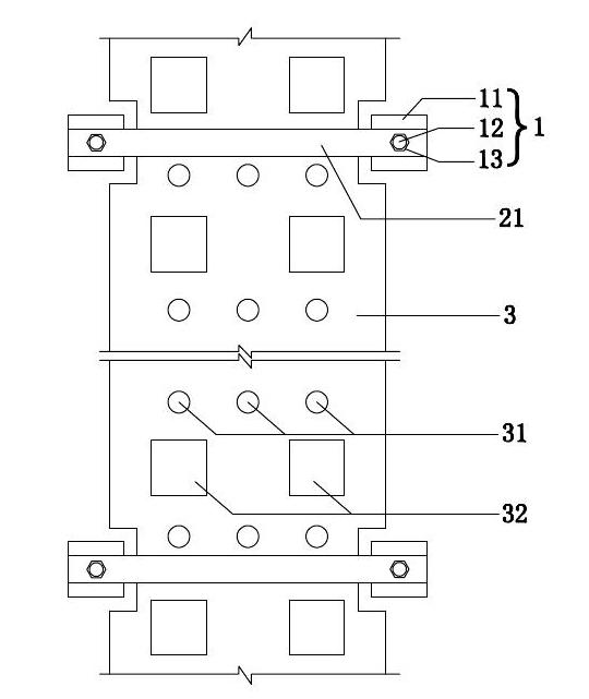
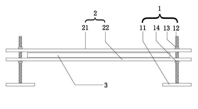
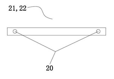
[0025] like Figure 1 to Figure 5 As shown, in this embodiment, the pre-embedded bolt bracket of the concrete foundation includes four sets of support components 1, two sets of clip steel plates 2 and steel formwork 3, and each set of support components 1 corresponds to one set of clip steel plates 2, of course, In this embodiment, it is not limited to four sets of support components 1 and two sets of clamping steel plates 2 , which can be appropriately increased according to the length of the steel template 3 .

[0026] Please continue to refer Figure 1 to Figure 5 , the support assembly 1 is arranged on the side of the steel formwork 3, and each set of support assemblies 1 includes a steel plate base 11, a screw rod 12 erected on the steel plate base 11, and an upper nut 13 and a lower nut screwed on the screw rod 12. Nut 14; wherein, the steel plate base 11 is a 20mm thick 200×100mm wide steel plate, and its width and thickness can be adjusted according to the actual situ...


PUM


Abstract

The invention discloses a concrete foundation embedded bolt bracket and an embedding method for concrete foundation embedded bolts. The embedded bolt bracket of a concrete foundation comprises at least four groups of support assemblies, at least two groups of clamping piece steel plates, steel templates, wherein every two groups of support assemblies correspond to a group of clamping piece steel plates; the support assemblies are arranged at the side parts of the steel templates; two ends of the clamping piece steel plates are movably connected with the support assemblies; the clamping piece steel plates comprise upper clamping piece steel plates and lower clamping piece steel plates; the steel templates are respectively clamped between every two clamping piece steel plates; and a plurality of bolt holes for allowing the embedded bolts to pass through are formed in the steel templates. According to the concrete foundation embedded bolt bracket and the embedding method for the concrete foundation embedded bolts, which are disclosed by the invention, the embedded bolts can be adjusted from six directions, the displacement and settlement of the embedded bolts caused by concrete construction are eliminated and high-precision embedding is realized, so that the embedding of the bolts is finished at one time and further the work efficiency is increased.

Description

technical field [0001] The invention relates to concrete foundation construction equipment for buildings, in particular to a pre-embedded bolt bracket for a concrete foundation and a method for pre-embedding bolts on a concrete foundation using the bracket. Background technique [0002] With the rapid development of my country's national economy, various large-scale industrial equipment installations and large-scale steel structure workshops continue to increase, and the number of pre-embedded bolts for various types of concrete foundations (especially large-scale industrial equipment concrete foundations) is increasing. In the prior art, there are two main methods for installing bolts on concrete foundations: one is to reserve bolt holes for installation of bolts, this method is more affected by construction quality factors, and small industrial equipment often adopts this method; the other is to pre-install Embedded bolts, large industrial equipment with large vibrat...

Claims


Application Information

Patent Timeline
Patent Type & Authority Applications(China)
IPC IPC(8): E02D27/44
Inventor 连贺古增密陈伟生宋登欣
Owner CHINA CONSTR FIFTH ENG DIV CORP LTD
Why Eureka
Try Eureka