Shock-proof mechanical magnetic lock

A magnetic lock and mechanical technology, applied in the field of locks, can solve the problems of easy locking of balls and pull bolts, easy breakage of return springs, poor impact resistance, etc., to reduce the probability of locking, improve safety, and simple opening structure Effect

Active Publication Date: 2012-08-01
SHANGHAI ONE TOP
View PDF7 Cites 6 Cited by
  • Summary
  • Abstract
  • Description
  • Claims
  • Application Information

AI Technical Summary

Problems solved by technology

Poor impact resistance, can not meet customer requirements
Often stuck, that is, easy to lock between the ball and the pull bolt
Two return springs are easy to break
There are defects in the design of the pad structure on the bottom connector. When the door rotates, the lock body does not rotate in multiple directions with the iron plate, and the force on the lock body is uneven, resulting in leverage, which is easy to be opened and has low safety.

Method used


Image

  • Shock-proof mechanical magnetic lock
  • Shock-proof mechanical magnetic lock
  • Shock-proof mechanical magnetic lock

Examples


Embodiment Construction

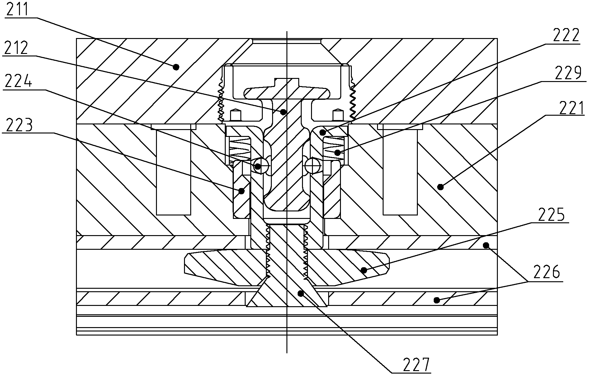
[0027] Such as image 3 with Figure 4 As shown, the shock-absorbing mechanical magnetic lock of the present invention includes an iron plate 211 on one side, a pull bolt 212 protruding vertically from the iron plate 211, and a magnet 221 on the other side, which is located in the magnet 221 and the top opening can Insert the sleeve 222 of the pull bolt 212 and the stop ring 223 sleeved on the periphery of the sleeve 222 . Wherein, the end of the pull bolt 212 forms a flange. The sleeve 222 and the stop ring 223 have a mechanism that cooperates with each other to adjust the aperture of the sleeve 222 internal cavity. On the other hand, a step is formed on the inner surface of the side wall of the snap ring 223, and the diameter of the upper portion of the inner cavity of the snap ring 223 is larger than that of the lower portion. The stop ring 223 is fixed on the magnet 221, and the bottom of the sleeve 222 can be rotatably installed on the base plate 226 below the magnet 2...


PUM


Abstract

The invention discloses a shock-proof mechanical magnetic lock, comprising an iron plate (211), a pulling plug (212), a magnet (221), a sleeve (222) and a stop ring (223), wherein the iron plate (211) is arranged at one side; the pulling plug (212) is vertically protruded from the iron plate (211); the magnet (221) is arranged at the other side; the sleeve (222) is arranged inside the magnet (221), and the pulling plug (212) can be inserted into the opening on the top of the sleeve (222); and the stop ring (223) is sleeved at the periphery of the sleeve (222); the stop ring (223) is fixed on the magnet (221); the sleeve (222) is installed on a baseplate (226) under the magnet (221) by a connecting piece (227); the magnet (221) and the stop ring (223) can make axial movement relative to the sleeve (222); and a spring (229) is arranged between the sleeve (222) and the stop ring (223). Through the improved structure, the service life, the shock resistance and the safety of the lock body are improved; and through the structure of the opening on the top of the sleeve (222), locking probability of internal balls is reduced and the cost of processing and assembly is lowered.

Description

technical field [0001] The invention relates to a lock, in particular to a shock-absorbing mechanical magnetic lock. Background technique [0002] A kind of existing shock-absorbing mechanical magnetic force lock such as figure 1 with figure 2 As shown, the iron plate 111 on one side of the lock body is provided with a vertically protruding pull bolt 112, and the magnet 121 on the other side includes a sleeve 122 whose top opening can be inserted into the pull bolt 112 and a sleeve 122 sleeved on the periphery of the sleeve 122. stop ring 123 . Wherein, the end of the pull bolt 112 forms a flange. The side wall of the sleeve 122 is provided with a plurality of round holes, and balls 124 are placed in each round hole. The diameter of the upper portion of the central hole of the stop ring 123 is larger than the diameter of the lower portion. The bottom of the sleeve 122 is fixed on the base plate 126 below the magnet 121 through the bottom connector 127 , the stop ring 1...

Claims


Application Information

Patent Timeline
Patent Type & Authority Applications(China)
IPC IPC(8): E05B47/02E05B15/00
CPCE05B15/00E05B47/02E05C19/166
Inventor 张宗志
Owner SHANGHAI ONE TOP
Why Eureka
Try Eureka