Hydraulic system flow collector with bypass function

A hydraulic system and fluid collector technology, which is applied to fluid pressure actuation system components, fluid pressure actuation devices, servo motor components, etc., can solve problems such as cumbersome installation and pipe joint leakage, reduce hydraulic system leakage, simplify The effect of piping connections

Inactive Publication Date: 2012-08-01
TIANJIN CHENGPU ENG MACHINERY
View PDF5 Cites 5 Cited by
  • Summary
  • Abstract
  • Description
  • Claims
  • Application Information

AI Technical Summary

Problems solved by technology

When the system is assembled, due to space constraints, the inlet and outlet tee pipe joints of the cooler 2 are connected to the inlet and outlet pipe joints of the bypass check valve 3 through steel pipes. prone to leakage

Method used


Image

  • Hydraulic system flow collector with bypass function
  • Hydraulic system flow collector with bypass function
  • Hydraulic system flow collector with bypass function

Examples


Embodiment Construction

[0012] In order to further understand the technical content, characteristics and effects of the present invention, the following examples are listed hereby, and detailed descriptions are as follows in conjunction with the accompanying drawings:

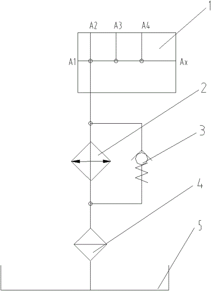
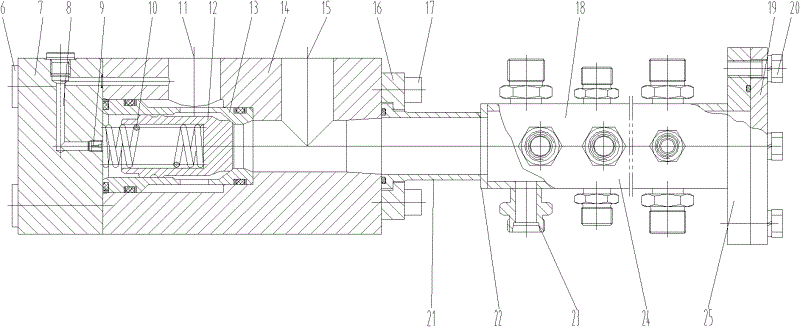
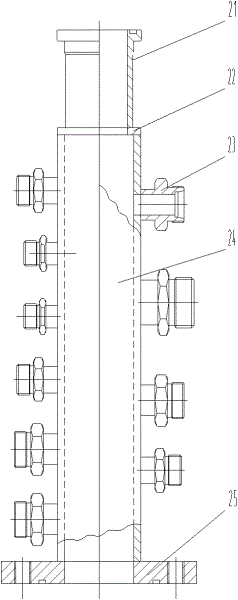
[0013] Refer to attached figure 2 , a hydraulic system collector with a bypass function, which is characterized in that it is composed of a collector 18, a flange cover 19 and a three-port safety valve, wherein the collector is provided with a joint body 23 for Connected to the oil return and drain of the hydraulic system, one end of the collecting pipe is connected to the oil inlet of the three-oil port safety valve, and the other end of the collecting pipe is blocked by the flange cover plate; the three-oil port safety valve The valve includes a cover plate 7, a damping plug 9, a spring 10, a valve core 12, a valve sleeve 13, and a valve body 14, wherein the cover plate is fixed on the valve body by screws, the valve sleeve is tigh...


PUM


Abstract

A hydraulic system flow collector with a bypass function is characterized by being formed by a flow collecting pipe, a flange cover plate and a three-oil-port safety valve. The flow collecting pipe is provided with a connector body and used for receiving returning oil and leaking oil of a hydraulic system. One end of the flow collecting pipe is connected with an oil feeding port of a three-oil-port safety valve, and the other end of the flow collecting pipe is plugged through the flange cover plate. The three-oil-port safety valve comprises a cover plate, a damp plug screw, a spring, a valve core, a valve sleeve and a sleeve body. The cover plate is fixed on a valve body through a screw, the valve sleeve is matched inside the valve body in sealing mode, the valve core is matched inside the valve sleeve in sealing mode, the spring is assembled inside the valve core, and one end of the spring butts against the valve core. The other end of the spring butts against the cover plate. A control flow channel is processed on the inner side of the cover plate, and the damping plug screw is screwed into the control flow channel. One side of the valve body connected with the flow collecting pipe is provided with an oil outlet, and the oil outlet is used for connecting a cooling device. An overflow port is arranged at a flow channel portion on the valve body corresponding to the middle of the valve core and the valve sleeve.

Description

technical field [0001] The invention belongs to the field of hydraulic systems, in particular to a hydraulic system collector with a bypass function. Background technique [0002] It is best for the hydraulic system to work in the range of 40-60°C (construction machinery is allowed to work below 80°C). When the temperature is higher than the above-mentioned temperature, a cooler is used to reduce the oil temperature. For the hydraulic system of construction machinery, the commonly used return oil cooling circuit is as attached figure 1 . Oil return and drain pipeline A through the hydraulic system 1 ...A X Enter the manifold block 1 (the manifold block refers to the valve block and pipeline where the oil is collected), enter the cooler 2 after confluence, and then return to the oil tank 5 through the oil filter 4, so as to realize the return oil cooling of the hydraulic system And the function of oil purification. In addition, a bypass check valve 3 is connected in para...

Claims


Application Information

Patent Timeline
Patent Type & Authority Applications(China)
IPC IPC(8): F15B21/04F15B13/00
Inventor 张嘉琦
Owner TIANJIN CHENGPU ENG MACHINERY
Why Eureka
Try Eureka