Pre-tightening device

A one-part, oblique wedge technology, applied in installation, friction clamping detachable fasteners, optics, etc., can solve the problems of inconvenient adjustment and maintenance, and achieve the effect of simple structure, good pre-tightening effect and simple operation

Inactive Publication Date: 2012-08-01
SUZHOU TANGFENG ELECTRICAL APPLIANCE
View PDF0 Cites 17 Cited by
  • Summary
  • Abstract
  • Description
  • Claims
  • Application Information

AI Technical Summary

Problems solved by technology

[0002] In the prior art, after the existing piezoelectric ceramic pre-tightening device is adjusted, it is firmly connected to the body and then reinforced with pins or screws and anti-loose glue to prevent the pre-tightening mechanism from loosening, so that future adjustment and maintenance It is very inconvenient, and special fixtures are required for adjustment, and when replacing piezoelectric ceramics, it is necessary to reprocess pin holes or screw holes on the body

Method used


Image

  • Pre-tightening device
  • Pre-tightening device
  • Pre-tightening device

Examples


Embodiment Construction

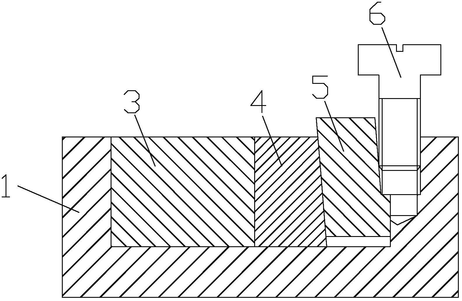
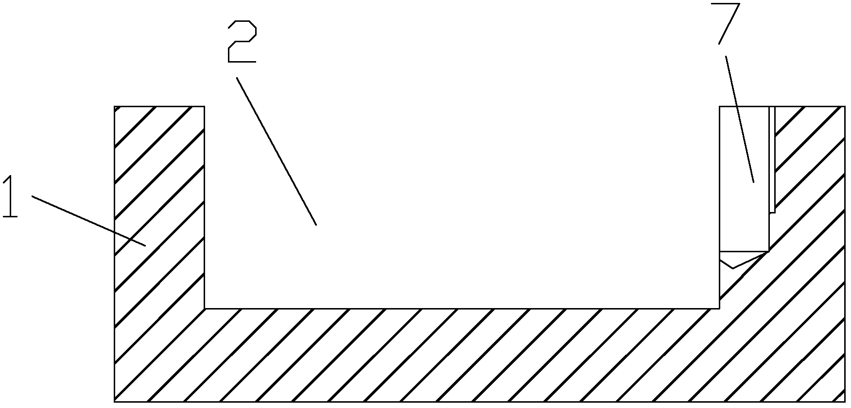
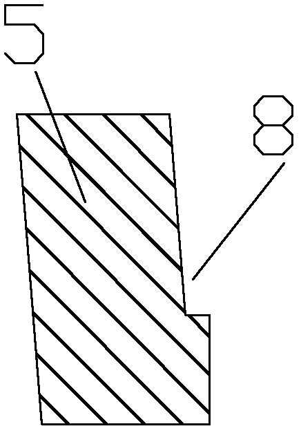
[0011] as attached figure 1 , 2 A pretensioning device according to the present invention shown in , 3 includes a body 1, a piezoelectric ceramic 3, a static wedge 4, a moving wedge 5, a screw 6, a screw hole 7, and a tapered hole 8; the body 1 is provided with a groove 2; the piezoelectric ceramic 3 is arranged on one side of the groove 2; one side of the piezoelectric ceramic 2 is adjacent to the side of the groove 2, and the other side is adjacent to the side of the static wedge 4. The vertical surfaces are adjacent; the other end of the groove 2 is provided with a screw hole 7; the moving cam 5 is inserted into the space between the static cam 4 and the other end of the groove 2; The inclined surface is adjacent to the inclined surface of the static wedge 4; the end of the vertical surface of the movable wedge 5 is provided with a tapered hole 8; the screw 6 is screwed into the screw hole 7, and a part of the screw 6 is also inserted into the tapered hole 8 ; When the sc...


PUM


Abstract

The invention discloses a pre-tightening device, which comprises a machine body, piezoelectric ceramics, a fixed wedge, a moving wedge, a screw, a screw hole and a conical hole. A groove is arranged on the machine body. The piezoelectric ceramics is arranged on one side of the groove. One side of the piezoelectric ceramics is adjacent to a side of the groove, and the other side of the piezoelectric ceramics is adjacent to a vertical face of the fixed wedge. The other end portion of the groove is provided with the screw hole. The moving wedge is inserted into a space between the fixed wedge and the other end of the groove. An inclined face of the moving wedge is adjacent to an inclined face of the fixed wedge. The conical hole is arranged at the end portion of the vertical face of the moving wedge. The screw is screwed into the screw hole, and one part of the screw is inserted into the conical hole too. When the screw is screwed downwards, the screw presses the moving wedge downwards to pre-tighten the piezoelectric ceramics. In the technical scheme, the screw is screwed into the screw hole, and one part of the screw is inserted into the conical hole too; and when the screw is screwed downwards, the screw presses the moving wedge downwards to pre-tighten the piezoelectric ceramics. The pre-tightening device is simple in structure and good in pre-tightening effect.

Description

technical field [0001] The invention relates to an improvement of a preloading device, in particular to a piezoelectric ceramic preloading device, and belongs to the technical field of preloading devices in precision optical positioning instruments. Background technique [0002] In the prior art, after the existing piezoelectric ceramic pre-tensioning device is adjusted, it is fixed on the body and then reinforced with pins or screws and then with anti-loosening glue to prevent the loosening of the pre-tensioning mechanism, which makes subsequent adjustment and maintenance. It is very inconvenient, and special fixtures are required for adjustment. When replacing piezoelectric ceramics, pin holes or screw holes need to be reworked on the body. SUMMARY OF THE INVENTION [0003] The purpose of the present invention is to provide a piezoelectric ceramic preloading device in order to overcome the deficiencies of the prior art. [0004] In order to achieve the above purpose, th...

Claims


Application Information

Patent Timeline
Patent Type & Authority Applications(China)
IPC IPC(8): F16B2/14G02B7/00
Inventor 唐祥根
Owner SUZHOU TANGFENG ELECTRICAL APPLIANCE
Why Eureka
Try Eureka