Backlight module and liquid crystal display device

A backlight module and backplane technology, which is applied to lighting devices, fixed lighting devices, components of lighting devices, etc., can solve the problems of reducing A value and affecting the display effect of the backlight module optical quality liquid crystal display device, etc. The effect of increasing the display area

Active Publication Date: 2012-08-01
TCL CHINA STAR OPTOELECTRONICS TECH CO LTD
View PDF7 Cites 24 Cited by
  • Summary
  • Abstract
  • Description
  • Claims
  • Application Information

AI Technical Summary

Problems solved by technology

Similarly, the backlight module of this structure also faces the problem of reducing the A value brought about by the narrow frame. If the narrow frame design exceeds the allowable range of the A value, that is, because the position of the LED 141 is fixed, the position of the light guide plate 120 The distance from the LED141 will decrease, resulting in a decrease in the A value, forming a firefly phenomenon in the display area of ​​the liquid crystal display device, thereby affecting the optical taste of the backlight module and the display effect of the liquid crystal display device

Method used


Image

  • Backlight module and liquid crystal display device
  • Backlight module and liquid crystal display device
  • Backlight module and liquid crystal display device

Examples


Embodiment 1

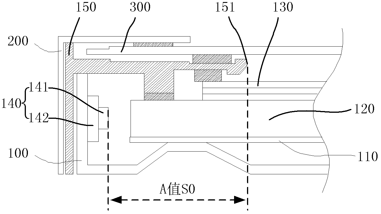
[0030] Such as Figure 4 Shown is Embodiment 1 of the present invention. The backlight module of the liquid crystal display device includes: a backplane 100, a reflection plate 110 placed on the backplane 100, a light bar 140 placed on the reflection plate 110 and opposite to the The light guide plate 120, the plastic frame 150 and the outer frame 200 arranged outside the back plate 100 and pressed together with the light guide plate 120, the optical film 130 is arranged on the light-emitting surface of the light guide plate 120, the liquid crystal panel 300 is composed of the plastic frame 150, the outer frame 200 and other components are fixed above the backlight module; wherein, the backplane 100 and the side walls of the plastic frame 150 are provided with through holes, and the through holes form a light-incident surface relative to the light guide plate 120 that extends outside the backlight module. Recess, the light bar 140 as a light source is set in the depression, an...

Embodiment 2

[0034] Such as Figure 5 Shown is the second embodiment of the present invention. The difference from the first embodiment is that in this example, the light bar 140 of the outer frame 200 is installed with a boss 210 extending toward the inside of the backlight module. The boss 210 Corresponding to the depression formed by the through holes on the back plate 100 and the plastic frame 150, the depth of the boss 210 is less than the sum of the thickness of the side wall of the back plate 100 and the thickness of the side wall of the plastic frame 150, and also That is to say, the boss 210 does not protrude from the concave surface of the depression and the bottom surface of the boss 210 is not flush with the concave surface, and the light bar 140 is installed on the bottom surface of the boss 210, The purpose of doing this is to facilitate positioning when the backlight module is assembled, and to improve the accuracy and efficiency of assembly. Such as Figure 5 As shown in ...

Embodiment 3

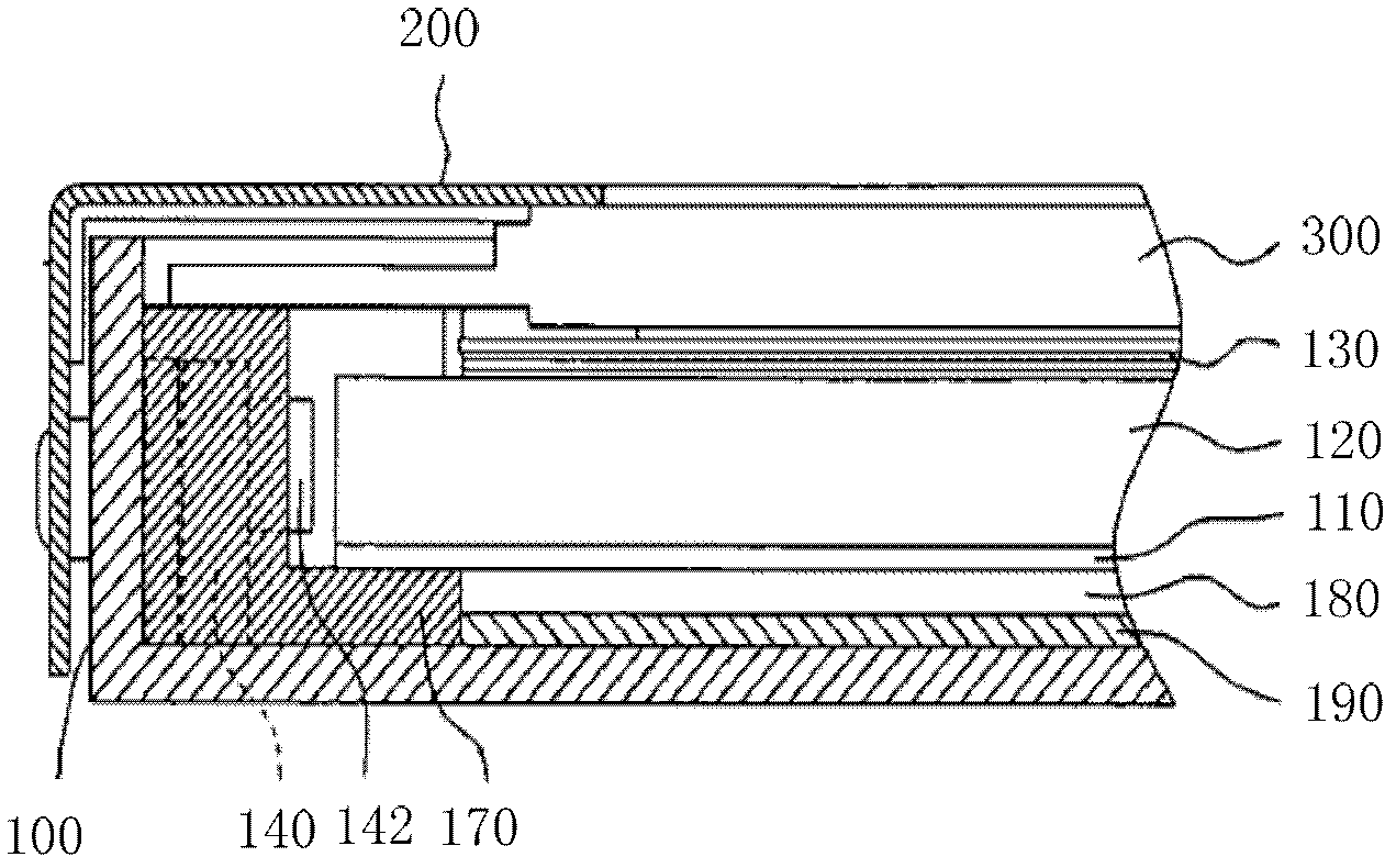
[0037] Such as Figure 6 Shown is the third embodiment of the present invention. In this embodiment, the backlight module of the liquid crystal display device includes: a back plate 100, a reflective plate 110 placed on the back plate 100, and a reflective plate 110 placed on the reflective plate 110. The light guide plate 120 facing the light bar 140 , the plastic frame 150 and the outer frame 200 arranged outside the back plate 100 and pressed against the light guide plate 120 , the optical film 130 is arranged on the light-emitting surface of the light guide plate 120 , and the liquid crystal panel 300 is composed of Components such as the plastic frame 150 and the outer frame 200 are fixed above the backlight module; wherein, the side wall of the plastic frame 150 is provided with a through groove corresponding to the installation position of the light bar 140, and the back plate 100 is provided with a curved groove at this position. fold 101, the bend 101 is submerged in ...


PUM


Abstract

The invention discloses a backlight module and a liquid crystal display device. The backlight module comprises a light guide plate, a light source and a back plate, wherein a depression which extends to the outside of the backlight module relative to the light incident surface of the light guide plate is arranged on the side wall of the back plate, and the light source is arranged in the depression. As the depression is arranged in the position of the fixed light source on the backlight module disclosed by the invention, the distance from the light source to the inner edge of a rubber frame is increased through the depression, namely that an A value is increased, so that a dark band region of light among luminous sources on the light source can be effectively eliminated and a hotspot phenomenon can be avoided in a display region of the liquid crystal display device. Simultaneously, after the A value is expanded, in order to realize a narrow side frame of the liquid crystal display device, the corresponding A value can be selected from a critical value of avoiding the hotspot phenomenon to the maximum A value obtained through the depression, thus the side frame of the liquid crystal display device can become narrower, and the display region of the liquid crystal display device is enlarged.

Description

technical field [0001] The invention relates to the field of liquid crystal display, more specifically, to a backlight module and a liquid crystal display device. Background technique [0002] The backlight module is one of the key components of the liquid crystal display device, which is mainly used to provide sufficient brightness and uniformly distributed light source so that the liquid crystal panel can display images normally. [0003] Such as figure 1 Shown is a backlight module of a liquid crystal display device, including: a back plate 100, a light bar 140 fixed on the side wall of the back plate 100, a reflector 110 placed on the back plate 100, and a reflector 110 placed between The light guide plate 120 on top and facing the light bar 140, the plastic frame 150 and the outer frame 200 arranged outside the back plate 100 and pressed against the light guide plate 120, the optical film 130 is arranged on the light-emitting surface of the light guide plate 120, and t...

Claims


Application Information

Patent Timeline
Patent Type & Authority Applications(China)
IPC IPC(8): F21S8/00F21V17/00F21V29/00G02F1/13357F21Y101/02
CPCG02F1/1335G02F1/133608G02F2001/133314G02F1/13G02F1/133615G02F1/133314G02F1/133317
Inventor 余亚军
Owner TCL CHINA STAR OPTOELECTRONICS TECH CO LTD
Why Eureka
Try Eureka