Backlight module, liquid crystal display device and light source of backlight module
A technology of backlight module and backplane, which is applied in the cooling/heating device, light source, electric light source, etc. The effect of temperature, saving thickness and increasing A value
- Summary
- Abstract
- Description
- Claims
- Application Information
AI Technical Summary
Problems solved by technology
Method used
Image
Examples
Embodiment 1
[0039] Such as Figure 4Shown is the first embodiment of the present invention, as shown in the figure is the light bar 140 of the backlight module, the light bar 140 includes: LED chip 145 and heat sink 144, the heat sink 144 includes: substrate 1441, set on The heat dissipation fins 1442 on the back of the substrate 1441 , the LED chip 145 is welded on the substrate 1441 , and the wiring is arranged on the substrate 1441 by etching. Among them, the substrate 1441 is made of metal material with good heat dissipation, such as aluminum, copper and other materials, and a layer of insulating layer is attached on the circuit layout surface to avoid circuit short circuit. Insulation layer, so that the heat of the light bar 140 can be conducted to the corresponding place in time by the heat sink 144, such as the aluminum extrusion, the back plate, and the heat emitted by the LED chip 145 on the light bar 140 is conducted in time, The temperature of the light bar 140 is reduced, the...
Embodiment 2
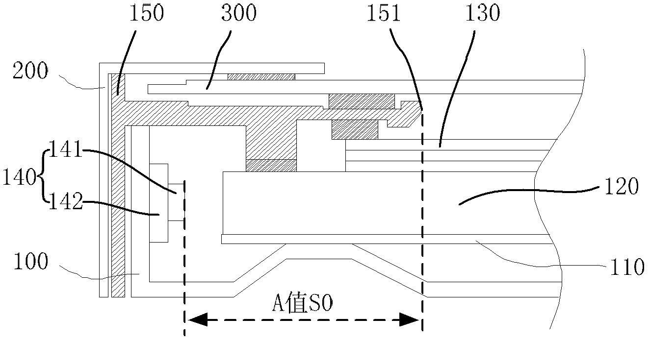
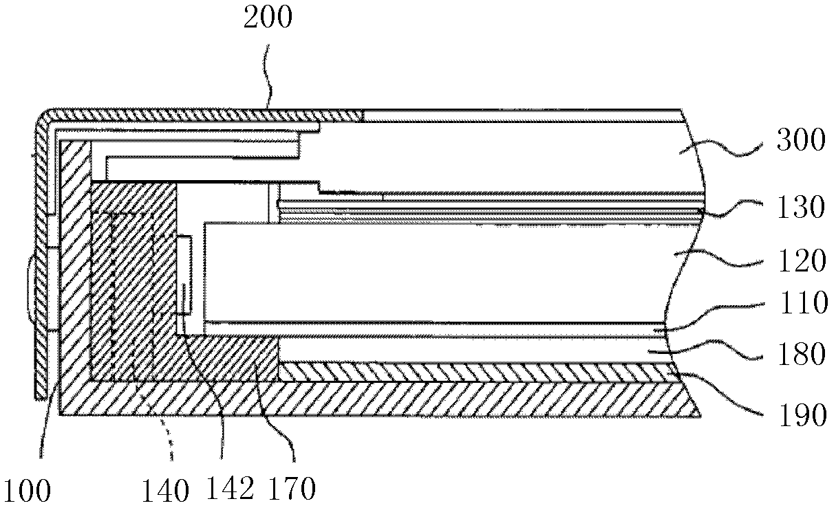
[0043] Such as Figure 5 Shown is the second embodiment of the present invention. As shown in the figure, the backlight module of the liquid crystal display device includes: a back plate 100, a reflective plate 110 placed on the back plate 100, and a reflective plate 110 placed on the reflective plate 110. The light guide plate 120 facing the light bar 140 , the plastic frame 150 and the outer frame 200 arranged outside the back plate 100 and pressed against the light guide plate 120 , the optical film 130 is arranged on the light-emitting surface of the light guide plate 120 , and the liquid crystal panel 300 is composed of Components such as the plastic frame 150 and the outer frame 200 are fixed above the backlight module; wherein, the light bar 140 is arranged on the backplane 100, and the light bar 140 is the light source described in the first embodiment. Such as Figure 5 As shown in , the side wall of the backplane 100 is provided with an embedding hole, the light bar...
Embodiment 3
[0048] Such as Image 6 Shown is the third embodiment of the present invention. In this embodiment, the plastic frame 150 is provided with a through groove corresponding to the installation position of the light bar 140, and the back plate 100 is provided with a bending structure 101 at this position to form a depression. The bent structure 101 is submerged in the through groove on the plastic frame 150, while the light bar 140 is directly installed on the bent structure 101 of the back plate 100. Similarly, the bent structure 101 is also provided with a light bar 140 The heat sink 144 of the light bar 140 is submerged in the embedded hole, so that the distance between the light bar 140 and the inner edge 151 of the plastic frame 150 is increased, so that the A value can be increased, thereby avoiding the firefly phenomenon in the liquid crystal It takes place in the display area of the display device (that is, the AA area). Such as Image 6 As shown in , the A value S2 of...
PUM
 Abstract
Description
Claims
Application Information
 - R&D
- Intellectual Property
- Life Sciences
- Materials
- Tech Scout
- Unparalleled Data Quality
- Higher Quality Content
- 60% Fewer Hallucinations
Browse by: Latest US Patents, China's latest patents, Technical Efficacy Thesaurus, Application Domain, Technology Topic, Popular Technical Reports.
© 2025 PatSnap. All rights reserved.Legal|Privacy policy|Modern Slavery Act Transparency Statement|Sitemap|About US| Contact US: help@patsnap.com


