Infrared touch screen for changing infrared light transmission paths and touch point recognizing method for infrared touch screen

An infrared touch screen and transmission path technology, applied in the input/output process of data processing, instruments, electrical digital data processing, etc., can solve the problems of anti-light interference, reduce the height and width of the raised edge of the infrared touch screen, and improve the appearance High degree, improve anti-light interference ability, easy to control the effect

Inactive Publication Date: 2012-08-01
GENERALTOUCH TECH
View PDF6 Cites 16 Cited by
  • Summary
  • Abstract
  • Description
  • Claims
  • Application Information

AI Technical Summary

Problems solved by technology

[0007] The purpose of the present invention is to overcome the above-mentioned problems existing in the existing infrared touch screen, and provide an infrared touch screen that changes the transmission path of infrared light and a method for identifying touch points thereof. After adopting the present invention, it can effectively reduce the levitation commonly existing in traditional infrared touch screens. The height problem can be basically not affected by external light, which can effectively solve the anti-light interference problem of traditional infrared touch screens, and can effectively reduce the height and width of the raised edges of existing infrared touch screens

Method used


Image

  • Infrared touch screen for changing infrared light transmission paths and touch point recognizing method for infrared touch screen
  • Infrared touch screen for changing infrared light transmission paths and touch point recognizing method for infrared touch screen
  • Infrared touch screen for changing infrared light transmission paths and touch point recognizing method for infrared touch screen

Examples


example 1

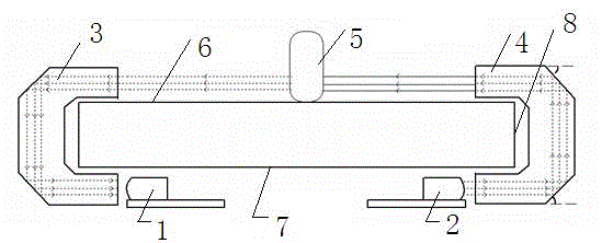
[0045] In this embodiment, the light guide column with a prismatic structure is used to implement light guide transmission. Such as figure 1 As shown, the infrared emitting unit 1 is an infrared emitting tube, and the infrared receiving unit 2 is an infrared receiving tube. After the infrared light emitted by the infrared emitting tube enters the emitting light guiding unit 3 perpendicular to the incident surface of the emitting light guiding unit 3, it reaches the first light guiding surface of the emitting light guiding unit, as long as the angle between the light guiding surface and the horizontal plane Set at 45°, the incident angle of infrared rays on its light guide surface is greater than the critical angle of total reflection of its light guide material (the critical angle of light incident from acrylic material or glass material to air is 42.8 ; light from PC material incident into air The critical angle is 39 ;), at this time, the infrared light transmitted inside t...

example 2

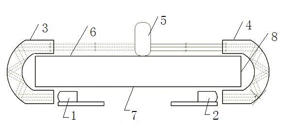
[0048] In this embodiment, the light guide column with a columnar structure is used to implement light guide transmission. Such as figure 2 As shown, after the infrared light emitted by the infrared emitting tube is perpendicular to the incident surface of the emitting light guiding unit 3 and enters the emitting light guiding unit 3, the radius of the arc surface of the emitting light guiding unit 3 is adjusted to make the incident light guiding unit 3 The incident angle of the infrared light on the curved surface of unit 3 is greater than the critical angle of total reflection (the critical angle of light incident from the plastic material to the air is 42.8·, the angle between the curved surface and the plane refers to the tangent of the curved surface and the plane Included angle), at this time, the infrared light can form total reflection inside the emission light guide unit 3, and the infrared rays will be emitted from the emission light guide unit 3 after multiple tota...

example 3

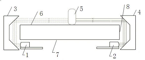
[0051] In this embodiment, a reflective light guide structure is used to implement light guide transmission, such as a mirror. Such as image 3 As shown, the infrared light emitted by the infrared emitting unit 1 is parallel to the horizontal direction and shoots towards the emitting light guide unit 3, as long as the angle between the first reflection surface and the second reflection surface of the emission light guide unit 3 and the horizontal plane is 45°, this When the infrared signal is reflected by the first reflective surface, it will shoot to the second reflective surface of the emitting light guide unit 3 in a direction perpendicular to the horizontal plane. After being reflected again, the light will be transmitted to the touch surface to form an infrared optical network, and then pass through The receiving light guiding unit 4 transmits to the infrared receiving unit 2 to be received by it in the same way, completing a complete transmitting and receiving system.

...


PUM


Abstract

The invention discloses an infrared touch screen for changing infrared light transmission paths and a touch point recognizing method for the infrared touch screen. In the touch screen, infrared light emitted by an infrared emission unit positioned on a non-touch face of the touch screen is changed in ray transmission direction by an emitting light guide unit prior to being transmitted to a touch face to form an infrared ray optical network, and then is changed in ray transmission direction by a receiving light guide unit prior to being transmitted to an infrared receiving unit of a non-touch face of the touch screen. By the aid of the infrared touch screen and the method, touch suspension height of the infrared touch screen is decreased, light interference resistance of the infrared touch screen is enhanced, and the protruded height and width of the edge of the touch face of the infrared touch screen are decreased.

Description

technical field [0001] The invention relates to an infrared touch screen, in particular to an infrared touch screen which changes an infrared light transmission path and a method for identifying a touch point. Background technique [0002] The existing infrared touch system adopts the infrared emission tubes and infrared receiving tubes arranged uniformly in the X and Y directions along the touch area, and the control and driving circuit drives the infrared emission under the control of the MCU execution code. The tube and the infrared receiving tube are scanned correspondingly to form an infrared matrix that crosses horizontally and vertically in the X direction and the Y direction. When there is a touch, fingers or other objects will block the horizontal and vertical infrared rays passing through the point, and the control system can judge the position of the touch point on the touch screen. [0003] At present, in the field of infrared touch screen, such as the patent No...

Claims


Application Information

Patent Timeline
Patent Type & Authority Applications(China)
IPC IPC(8): G06F3/042
Inventor 钟德超唐海卫蒲彩林
Owner GENERALTOUCH TECH
Why Eureka
Try Eureka