Z-axis lifting mechanism with stress state balancing function

A technology of stress state and lifting mechanism, which is applied in the direction of mechanical equipment, conveyor objects, belts/chains/gears, etc., can solve the problems of large and micro deformation of ball guide rails, short service life of ball guide rails, and complicated processing technology of columns, etc., to achieve Correct the problem of unstable center of gravity, the effect of strong load capacity and stable center of gravity

Inactive Publication Date: 2012-08-01
HARBIN INST OF TECH
View PDF5 Cites 16 Cited by
  • Summary
  • Abstract
  • Description
  • Claims
  • Application Information

AI Technical Summary

Problems solved by technology

[0003] The purpose of the present invention is to solve the problem that the Z-axis drive lifting mechanism of the existing silicon wafer transfer robot has poor structural stress state, large microscopic deformation of the ball guide rail, short service l

Method used


Image

  • Z-axis lifting mechanism with stress state balancing function
  • Z-axis lifting mechanism with stress state balancing function
  • Z-axis lifting mechanism with stress state balancing function

Examples


specific Embodiment approach 1

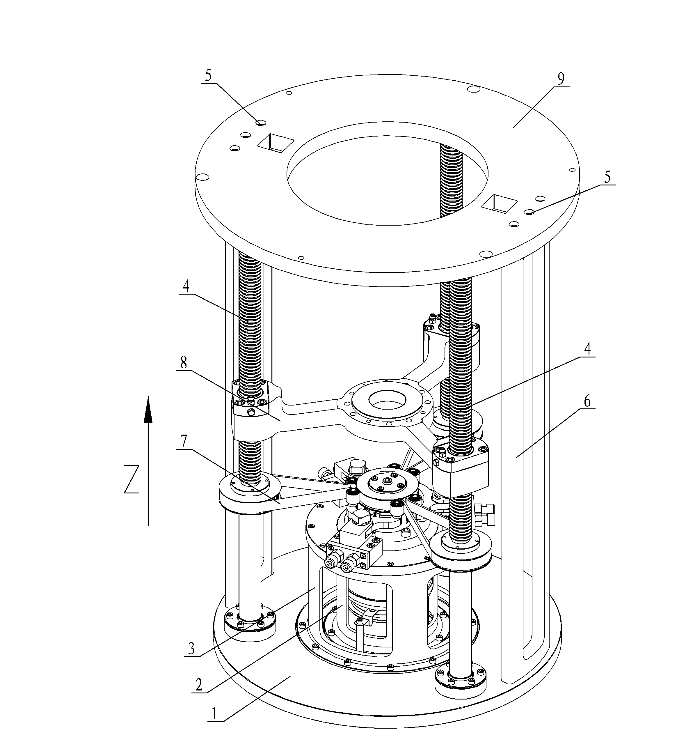
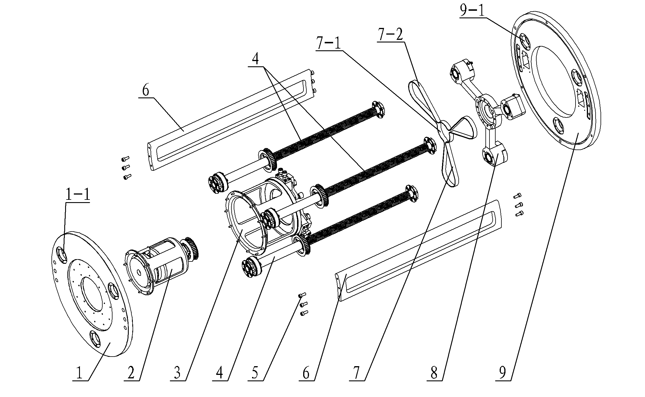
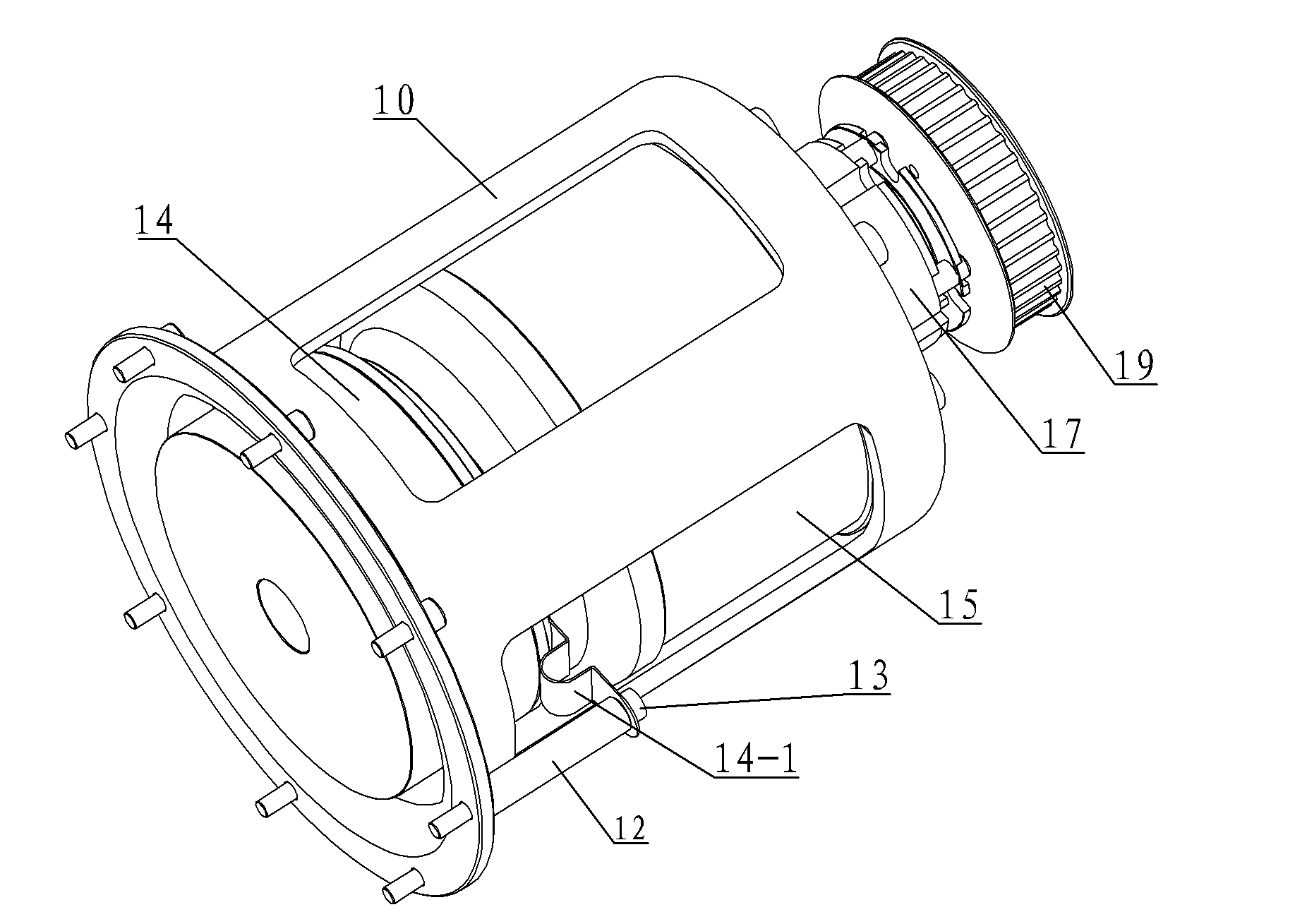
[0007] Specific implementation mode one: combine Figure 1 to Figure 8 Describe this embodiment, which includes a lower mounting base 1, a Z-axis drive assembly 2, a pretensioner support mechanism 3, a synchronous tooth transmission belt 7, a nut transmission mechanism 8, an upper mounting cover 9, two connecting plates 6 and Three screw drives 4, see image 3 and Figure 4 : Z-axis driving device assembly 2 includes Z-axis motor base 10, encoder positioning tube 12, encoder 14, Z-axis servo motor 15, friction brake 17, synchronous transmission driving gear 19 and connecting plate 20, the Z-axis servo The upper end of the motor 15 shaft is an output shaft 15-1, and the lower end is a motor shaft 15-2, and the Z-axis servo motor 15 is installed in the Z-axis motor seat 10 by a screw 16, and the output shaft 15-1 of the Z-axis servo motor 15- 1 is located outside the Z-axis motor base 10, and the upper end of the output shaft 15-1 is provided with a transmission external tooth...

specific Embodiment approach 2

[0008] Specific implementation mode two: combination Figure 6 Describe this embodiment, each pretension wheel mechanism 38 of this embodiment includes a pretension wheel shaft 39, a pretension wheel 41, a shaft circlip 42 and two pretension wheel bearings 40, and the pretension wheel 41 A preload wheel bearing 40 is respectively installed at the upper and lower recesses of the inner cavity, the preload wheel 41 is installed on the preload wheel shaft 39, and the shaft circlip 42 is installed on the upper end of the preload wheel shaft 39 exposed on the preload wheel 41 upper end surface. In the groove, the circlip 42 for the shaft is used to fix the relative position of the pretensioner bearing 40 . Other components and connections are the same as those in the first embodiment.

[0009] The working principle of the present invention is: when the Z-axis servo motor 15 is running, the encoder 14 installed on the motor shaft 15-2 at the lower end of the Z-axis servo motor 15 st...


PUM


Abstract

A Z-axis lifting mechanism with a stress state balancing function relates to the manufacturing field of semiconductor silicon wafer transmission robots, and solves the problems of a conventional Z-axis transmission lifting mechanism, such as poor structural stress state and larger micro-deformation of ball guide rails. The Z-axis lifting mechanism with the stress state balancing function adopts the structure that an upper mounting cover and a lower mounting cover are oppositely arranged up and down, a Z-axis driving device component is connected with a lower mounting seat, a pre-tightening wheel support frame is sleeved on the Z-axis driving device component and connected with the lower mounting seat, three lead screw transmission mechanisms are uniformly distributed between the upper mounting cover and the lower mounting cover along the same circumference, the center end of a synchronous gear transmission belt is sleeved on a synchronous transmission driving gear, three outer side ends of the synchronous gear transmission belt are respectively sleeved on three synchronous transmission driven gears, three ball screws are respectively in threaded connected with three turn-screws; a lower deep-groove ball bearing is mounted in a lower bearing mounting hole of the lower mounting seat, and an upper deep-groove ball bearing is mounted in an upper bearing mounting hole. The Z-axis lifting mechanism provided by the invention is used on a silicon chip transmission robot.

Description

technical field [0001] The invention relates to the manufacturing field of a semiconductor silicon wafer transmission robot, in particular to a Z-axis transmission lifting mechanism on a silicon wafer transmission robot. Background technique [0002] In the Z-axis transmission lifting mechanism of the silicon wafer transfer robot, the column type Z-axis transmission lifting mechanism is mostly used, that is, the ball guide rail is used as the movement reference of the Z-axis lifting, and the ball guide rail is installed on the reference surface of the column. But there is following shortcoming in this transmission mechanism: the one, the stressed state of structure is bad. The force direction of the column-type Z-axis transmission lifting mechanism is along the motion axis of the ball guide rail, and the best force direction of the guide rail is in the vertical direction to the plane of the ball guide rail; The block is transmitted to the ball guide rail in the form of a ca...

Claims


Application Information

Patent Timeline
IPC IPC(8): H01L21/677F16H37/02F16H25/22
CPCF16H37/02F16H25/22F16H25/20F16H25/2204F16H2025/2053F16H2025/2096
Inventor 刘延杰吴明月荣伟彬孙立宁
Owner HARBIN INST OF TECH
Why Eureka
Try Eureka