Z-axis transmission structure

A transmission structure, Z-axis technology, applied in the direction of transmission, conveyor objects, belts/chains/gears, etc., can solve the problems of complicated column processing technology, large contact area, difficult adjustment, etc., to correct the problem of unstable center of gravity, Reasonable structure of Z-axis transmission to ensure the effect of assembly accuracy

Inactive Publication Date: 2014-02-12
HARBIN INST OF TECH
View PDF5 Cites 0 Cited by
  • Summary
  • Abstract
  • Description
  • Claims
  • Application Information

AI Technical Summary

Problems solved by technology

But this kind of transmission structure has the following disadvantages: one is that the structural stress state is not good
Since the entire weight of the T-axis and R-axis is transmitted to the ball guide rail in the form of a cantilever beam through the T-axis support slider, the ball guide rail also bears a large overturning moment in addition to the normal bearing gravity, causing the ball guide rail to generate a large The microscopic deformation will affect the flexibility of the movement at least, and shorten the service life of the ball guide
The second is that there are complex shape and position tolerances between the installation surface of the ball guide rail and the lateral positioning surface, between the upper and lower installation and positioning surfaces of the column, and between the installation surface of the ball guide rail and the installation datum of the ball screw. Complex process, low yield and high processing cost
Third, because the weight of the column is generally more than ten kilograms, and the surface is installed on one side of the chassis, it will inevitably cause the center of gravity to be unstable, which will easily cause the host to overturn
Fourth, due to the large contact area between the upper and lower mounting surfaces of the column and the upper and lower mounting plates of the main engine, it is difficult to adjust during assembly, which is time-consuming and laborious

Method used


Image

  • Z-axis transmission structure

Examples


Embodiment Construction

[0018] The present invention will be further described in conjunction with accompanying drawing:

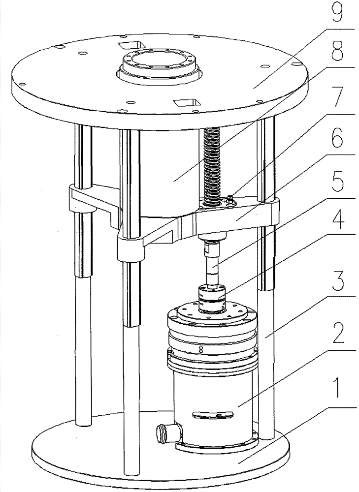
[0019] refer to figure 1 As shown, a high-precision, load-balanced Z-axis transmission structure includes a lower mounting seat 1, a Z-axis driving device combination 2, an LF-type linear ball spline shaft / linear ball bushing combination 3, a flexible coupling 4, Ball screw 5, triangular support sliding sleeve 6, ball screw nut assembly 7, T-axis mechanism combination 8, upper mounting cover 9, etc.

[0020] A high-precision, load-balanced Z-axis transmission structure is characterized by using a triangular support sliding sleeve 6 and three sets of LF-type linear ball spline shaft / linear ball bushing combination 3 to replace the column. Since the LF type linear ball spline shaft / linear ball bushing combination 3 has high transmission accuracy and is uniformly distributed at 120° in the installation circle, the 6 triangular support sliding sleeves can bear the T-axis and R-axis ...


PUM


Abstract

The invention relates to a Z-axis transmission structure. A triangular support sliding sleeve (6) and three sets of LF-type linear roll ball spline shafts / linear roll ball bushing combinations (3) are used to replace a vertical post and serve as a main body support structure. Since the LF-type linear roll ball spline shafts / linear roll ball bushing combinations (3) have higher transmission precision and are uniformly distributed in the circumference at an angle of 120 degrees, the triangular support sliding sleeve (6) only uniformly bears the weight of a T-axis mechanism and an R-axis mechanism, cannot generate an extra turning torque due to non-uniform applied force, and the stress state is greatly improved to make the Z-axis transmission structure more reasonable.

Description

technical field [0001] The invention relates to a triangular support with higher transmission precision, uniform distribution of transmission load on the circumference, light weight, small volume and space saving compared with the column type Z-axis transmission structure in the field of semiconductor silicon wafer transmission robot manufacturing Type Z-axis transmission structure. Background technique [0002] In the Z-axis transmission structure of the silicon wafer transfer robot, most of the domestic use the column type Z-axis transmission structure, that is, the ball guide rail is used as the motion reference of the Z-axis transmission, and the ball guide rail is installed on the reference surface of the column. But there is following shortcoming in this transmission structure: the one, the stressed state of structure is bad. Since the entire weight of the T-axis and R-axis is transmitted to the ball guide rail in the form of a cantilever beam through the T-axis suppo...

Claims


Application Information

Patent Timeline
Patent Type & Authority Patents(China)
IPC IPC(8): F16H25/22F16H25/24H01L21/677
Inventor 刘延杰吴明月荣伟彬孙立宁
Owner HARBIN INST OF TECH
Why Eureka
Try Eureka