Switching controller for flyback type power converter and the controller and control circuit thereof

A power converter and switching circuit technology, applied in output power conversion devices, conversion of DC power input to DC power output, control/regulation systems, etc., can solve high output line ripple nonlinear power conversion operations, large space And other issues

Active Publication Date: 2012-08-01
SYST GEN
View PDF3 Cites 5 Cited by
  • Summary
  • Abstract
  • Description
  • Claims
  • Application Information

AI Technical Summary

Problems solved by technology

When there is no filtering effect of the input capacitor 36, the pulsating DC input voltage V IN Will result in higher output line ripple an...

Method used


Image

  • Switching controller for flyback type power converter and the controller and control circuit thereof
  • Switching controller for flyback type power converter and the controller and control circuit thereof
  • Switching controller for flyback type power converter and the controller and control circuit thereof

Examples


Embodiment Construction

[0121] In order to make the above objects, features and advantages of the present invention more comprehensible, a preferred embodiment will be described in detail below together with the accompanying drawings.

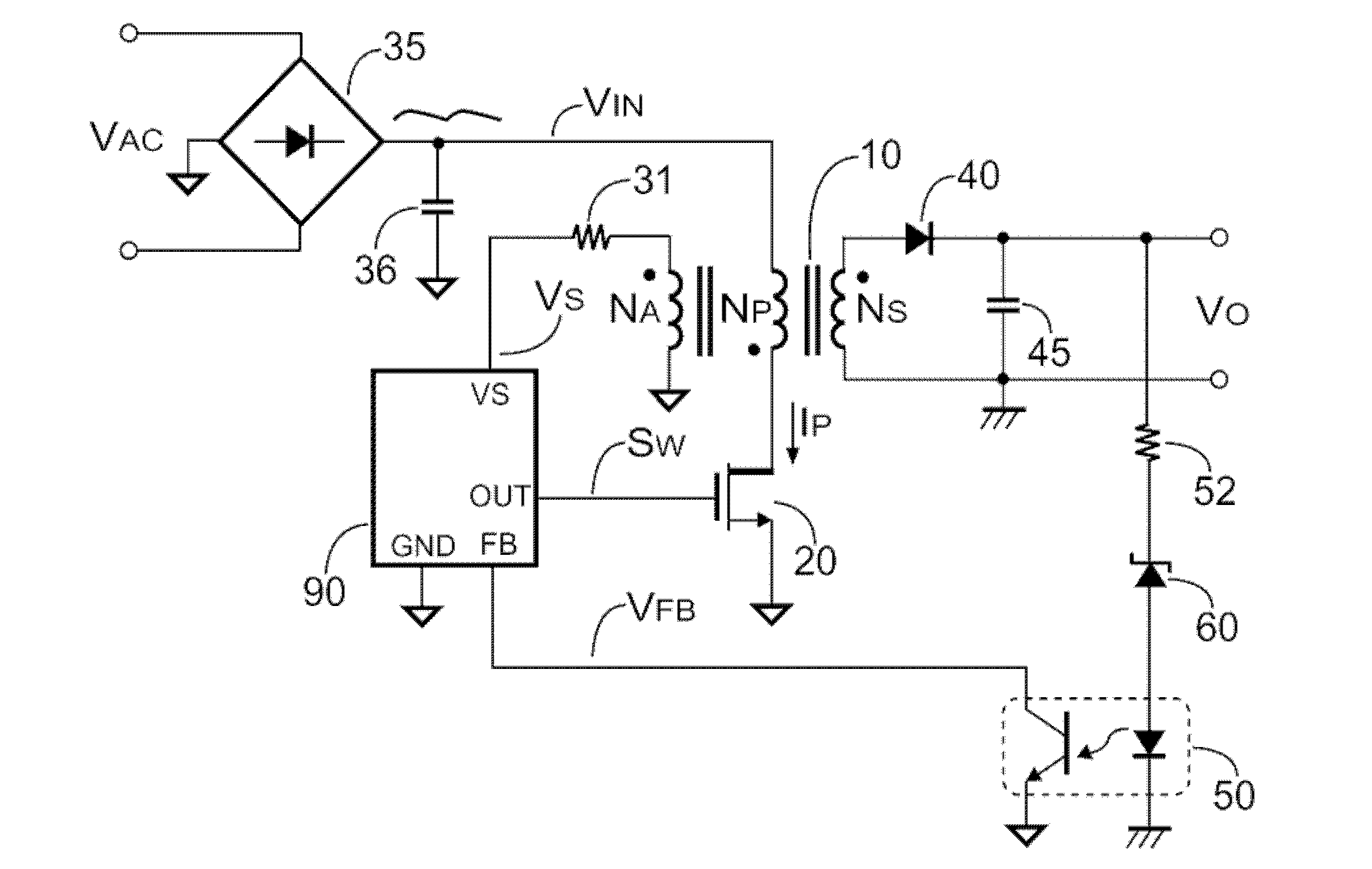
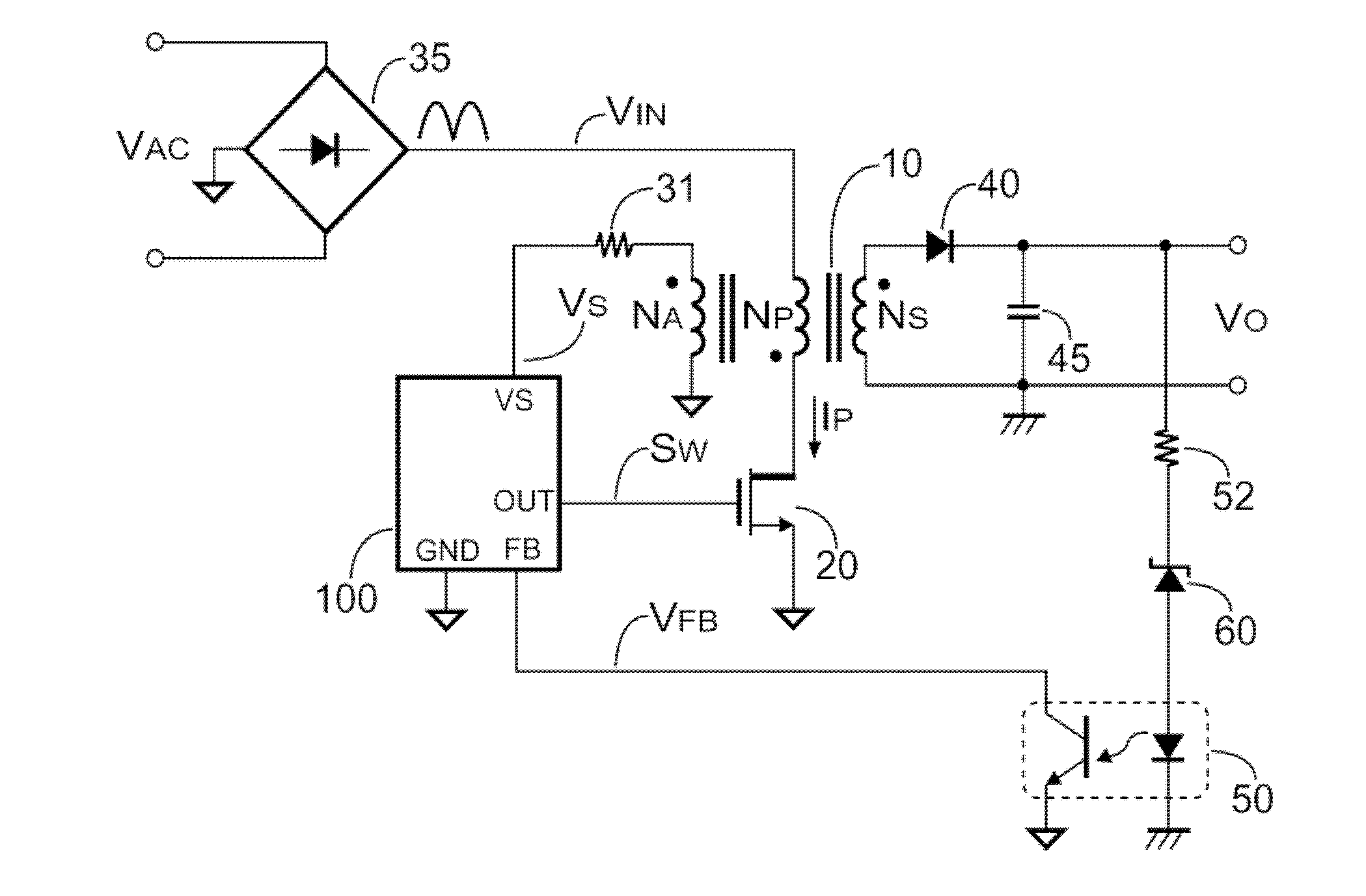
[0122] Figure 1B is a flyback power converter according to an embodiment of the present invention. Figure 1A and Figure 1B The only difference between Figure 1B The embodiment is to use switching controller 100 without using Figure 1A input capacitor 36 to perform general output regulation of the power converter.

[0123] The output power P of the flyback power converter O Can be expressed as:

[0124] P O = V O × I O = V IN 2 × T ON 2 ...


PUM


Abstract

Provided is a switching controller for a flyback type power converter, comprising a switching circuit, a sampling maintaining circuit, a voltage detecting circuit, an oscillator, and a comparator. When the input voltage of the flyback type power converter is lower than the low threshold, the voltage detecting circuit generates maintaining signals. The maintaining signals are generated based on the output voltage of the flyback type power converter. An oscillating circuit limits the maximum frequency of the switching signals. The maximum frequency is increased with the decrease of the adjusting signals. When the level of the input voltage is lower than the minimum threshold, the adjusting signals associated with the level of the input voltage are used for generating control signals. The control signals are used for making the flyback type power converter operate under the operation of the continuous current mode. Therefore, the usage of an input capacitor can be avoided and the making cost is cut down.

Description

technical field [0001] The present invention relates to a power converter, in particular to a switching control circuit of a flyback power converter. Background technique [0002] Figure 1A is a known flyback power converter. The power converter includes a bridge rectifier 35 , an input capacitor 36 , a controller 90 , a transformer 10 , a power transistor 20 , a sense resistor 31 , a rectifier 40 , an output capacitor 45 and a secondary side feedback circuit. The transformer 10 includes a primary side coil N P , Secondary coil N S and auxiliary coil N A . The secondary side feedback circuit includes a resistor 52 , a Zener diode (as a voltage regulator) 60 , and an optocoupler 50 . The bridge rectifier 35 converts an alternating current (AC) input voltage V AC Converted to a pulsating direct current (DC) input voltage (pulsating direct current (DC) input voltage) V IN . This input voltage V IN It is also filtered by the input capacitor 36 to become a nearly DC inp...

Claims


Application Information

Patent Timeline
IPC IPC(8): H02M3/335
CPCH02M2001/0022H02M3/33507H02M1/0022
Inventor 杨大勇林立林昭志
Owner SYST GEN
Why Eureka
Try Eureka