Milling mechanism of pipe cutting machine

A pipe cutting machine and milling technology, which is applied to metal sawing equipment, sawing machine equipment, metal processing equipment, etc., can solve the problems of high cutting noise, low safety, and many incision burrs, and achieves low vibration and extended saw blades. Longevity, smooth incision without burr

Inactive Publication Date: 2012-08-08
江苏中港冶金设备科技有限公司
View PDF5 Cites 0 Cited by
  • Summary
  • Abstract
  • Description
  • Claims
  • Application Information

AI Technical Summary

Problems solved by technology

This kind of milling mechanism not only has many burrs and uneven incision after cutting, but also has high cutting noise; moreover, because the rack reciprocates beyond the bed, it requires a large working space and low safety

Method used


Image

  • Milling mechanism of pipe cutting machine
  • Milling mechanism of pipe cutting machine
  • Milling mechanism of pipe cutting machine

Examples


Embodiment 1

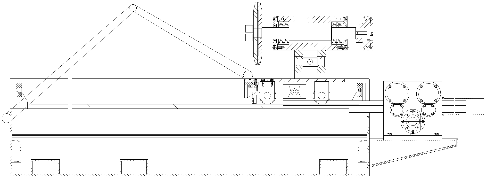
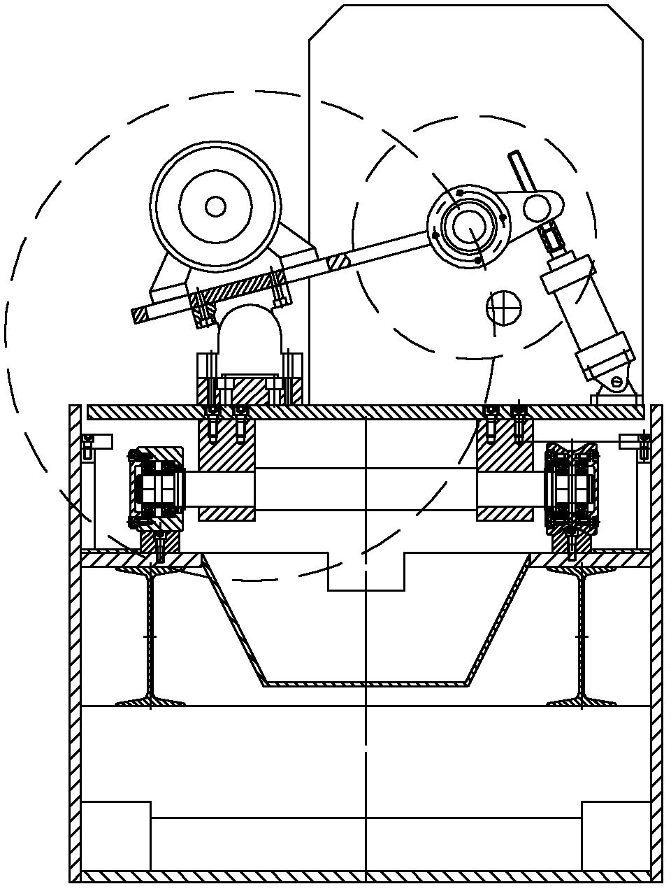
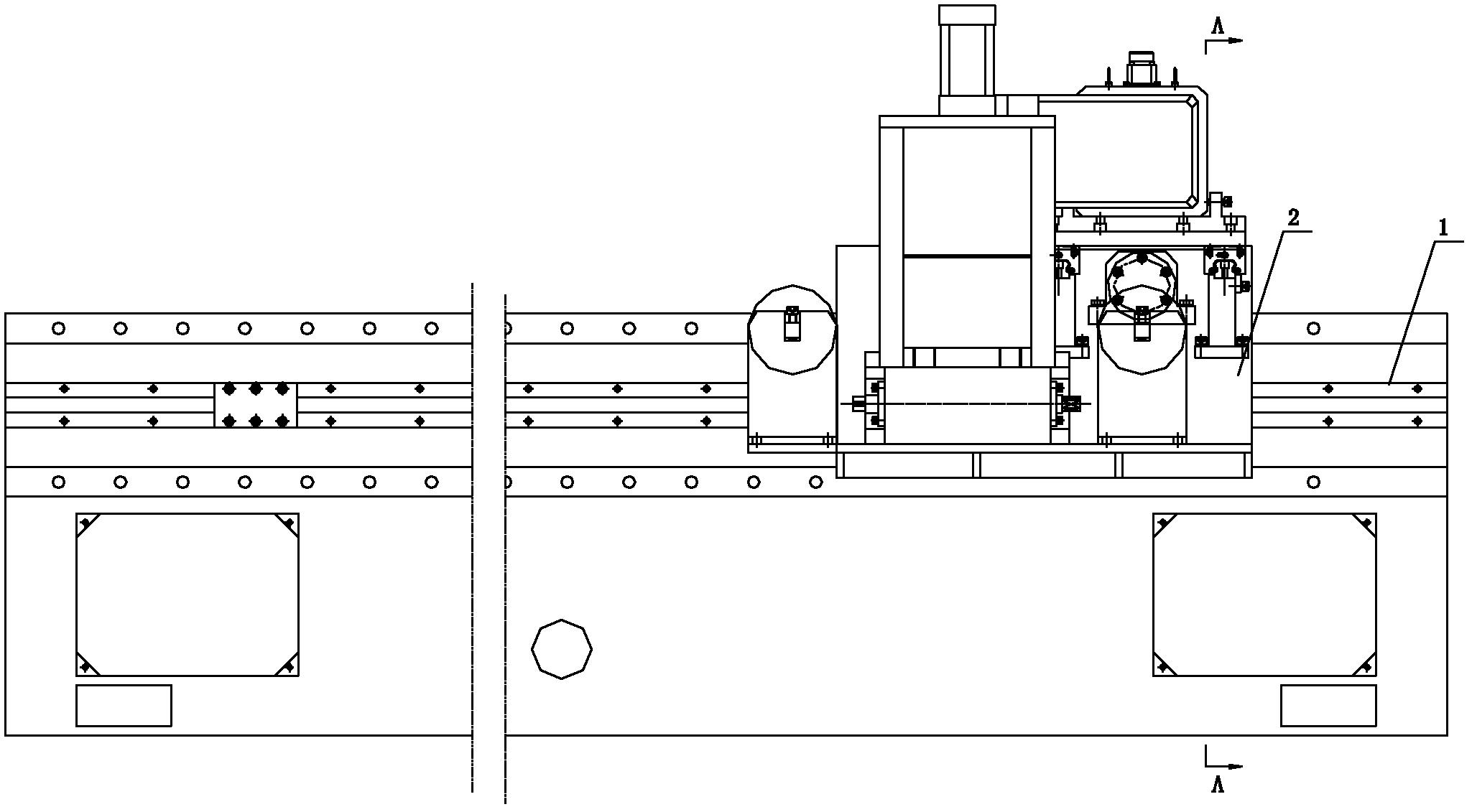
[0037] Example 1 as Figure 3-6 As shown, a milling mechanism of a pipe cutting machine includes a base 2, a guide block 18 is arranged on the lower part of the base 2, and the base 2 is connected with a linear guide rail 17 provided on the pipe cutting machine frame 1 through the guide block 18. The base 2 is provided with a leading screw 3, the end of the leading screw 3 is provided with a first variable speed motor 4, a sliding seat 5 is movable on the leading screw 3, a slide plate 6 is arranged on the sliding seat 5, and a plurality of slide plates are arranged on the slide plate 6. The guide block 13, the guide block 13 cooperates with the two guide rails 12 arranged on the base 2. The slide plate 6 is provided with a second variable speed motor 7 and a deceleration device 8 connected to the second variable speed motor 7, the deceleration device 8 is a speed reducer, and the second variable speed motor 7 is directly connected with the speed reducer. A clamping disc 10 a...

Embodiment 2

[0043] Example 2 as Figure 7-9As shown, a milling mechanism of a pipe cutting machine includes a base 2, a guide block 18 is arranged on the lower part of the base 2, and the base 2 is connected with a linear guide rail 17 provided on the pipe cutting machine frame 1 through the guide block 18. The base 2 is provided with a leading screw 3, the end of the leading screw 3 is provided with a first variable speed motor 4, a sliding seat 5 is movable on the leading screw 3, a slide plate 6 is arranged on the sliding seat 5, and a plurality of slide plates are arranged on the slide plate 6. A guide block (not shown in the figure), the guide block cooperates with the two guide rails 12 arranged on the base 2 . The slide plate 6 is provided with a second variable speed motor 7 and a reduction gear 8 connected with the second variable speed motor 7, the reduction gear 8 is a gear reduction box, and the second variable speed motor 7 is connected with the gear reduction box by a pair o...


PUM


Abstract

The invention discloses a milling mechanism of a pipe cutting machine. The milling mechanism comprises a base which is arranged on a rack of the pipe cutting machine; the base is provided with a lead screw; a first variable-speed motor is arranged at the end part of the lead screw; a sliding seat is movably arranged on the lead screw and is provided with a sliding plate; the sliding plate is provided with a second variable-speed motor and a speed reducing device connected with the second variable-speed motor; and an output shaft of the speed reducing device is provided with a saw blade. The milling mechanism of the pipe cutting machine, provided by the invention, has the advantages that the cut is smooth without burrs, the cutting noise is low, the structure is compact and the use is safe.

Description

technical field [0001] The invention relates to a pipe cutting machine, in particular to a milling mechanism of the pipe cutting machine. Background technique [0002] At present, the milling mechanism of ordinary pipe cutting machines mostly uses sawing machine sawing, grinding wheel cutting, and roller extrusion. Flat, many burrs, many chips, high noise and other shortcomings. [0003] Especially when the milling mechanism of these pipe cutting machines is used in the production process of high-frequency longitudinal welded pipes, especially when it is used for special-shaped pipes such as square pipes, these shortcomings affect the cutting quality more seriously. Moreover, the milling mechanism of ordinary pipe cutting machines is difficult to match the output speed of pipes on the production line. [0004] Such as Figure 1-2 As shown, it is a milling mechanism of a pipe cutting machine used in the production of high-frequency straight seam welded pipes. The tool seat ...

Claims


Application Information

Patent Timeline
IPC IPC(8): B23D45/12B23D47/12
Inventor 卢千祥刘红光蒋龙
Owner 江苏中港冶金设备科技有限公司
Why Eureka
Try Eureka