Automatic crystal grinding and polishing machine

A grinding and polishing machine, fully automatic technology, applied in the direction of grinding/polishing equipment, machine tools suitable for grinding the edge of workpieces, grinding machines, etc., can solve hidden dangers of personal health, can not realize the function of completely unattended, crystal grinding and polishing machine Incomplete and other problems, to achieve the effect of close cooperation between equipment and work

Inactive Publication Date: 2012-08-08
骆影文 +1
5 Cites 4 Cited by

AI-Extracted Technical Summary

Problems solved by technology

[0007] The purpose of the present invention is to overcome the defect that the prior art crystal polishing machine is not perfect in function, cannot realize the completely unattended function and has h...

Abstract

The invention discloses an automatic crystal grinding and polishing machine. A vibratory feeding device, a manipulator rotating and moving device, manipulator lifting and picking devices, an abutting feeding and preparing device, a semispherical grinding and polishing integrated device I, an abutting preparing and discharging device and a semispherical grinding and polishing integrated device II are arranged on a machine frame, wherein one manipulator lifting and picking device is arranged on each of the four corners of the manipulator rotating and moving device; four working mechanisms, namely the abutting feeding and preparing device, the semispherical grinding and polishing integrated device II, the semispherical grinding and polishing integrated device I and the abutting preparing and discharging device, are sequentially arranged under one of the manipulator lifting and picking devices anticlockwise; and the vibratory feeding device is arranged on the outer side of the abutting feeding and preparing device and is matched with the abutting feeding and preparing device for operation. According to the invention, the position relationship between the working mechanisms is skillfully designed, so that the devices can work smoothly in a tight fit way, without stop, thereby really realizing an unwatched, full-automatic, energy-saving and environment-friendly idea.

Application Domain

Edge grinding machines

Technology Topic

ManipulatorEngineering +2

Image

  • Automatic crystal grinding and polishing machine
  • Automatic crystal grinding and polishing machine
  • Automatic crystal grinding and polishing machine

Examples

  • Experimental program(1)

Example Embodiment

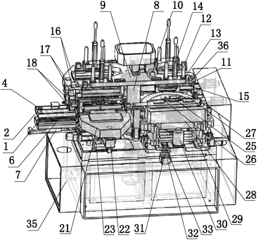
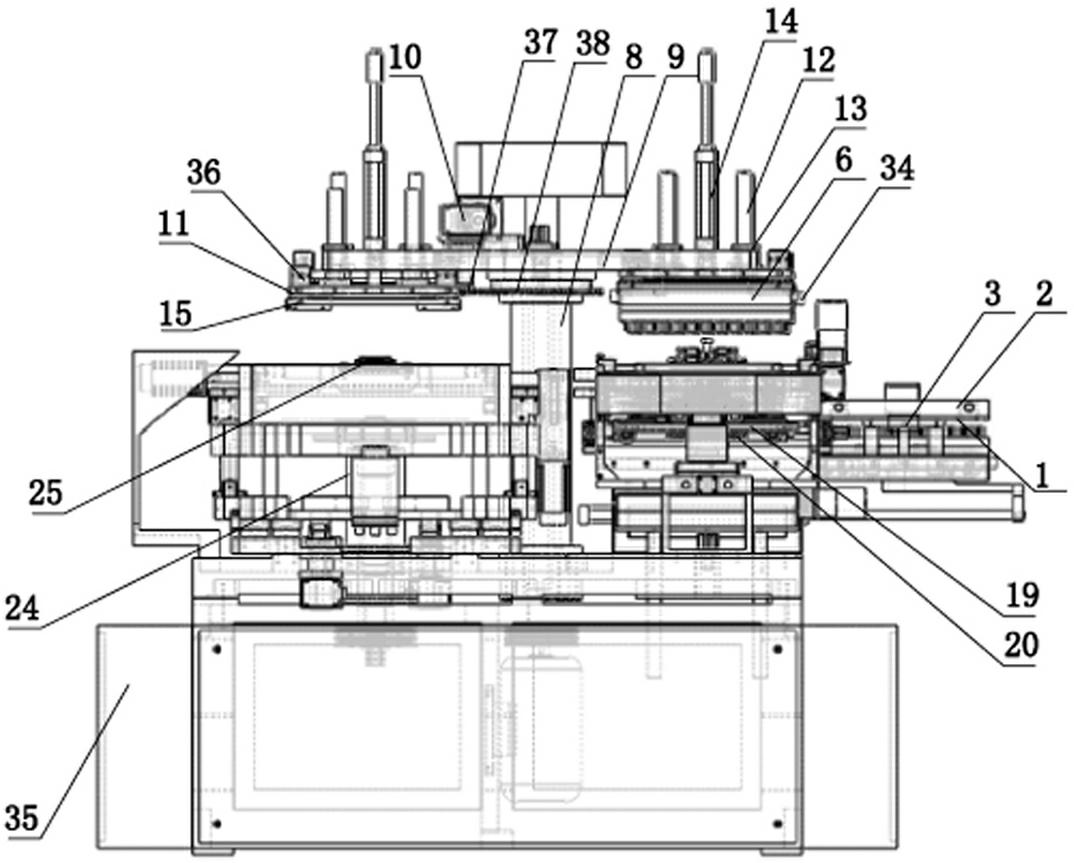
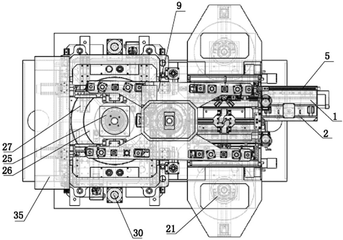
[0040] Example: such as figure 1 , figure 2 and image 3 As shown, the fully automatic crystal grinding and polishing machine of the present invention can be roughly divided into the following parts from the structure: vibrating feeding device, manipulator rotating and shifting device, manipulator lifting and grabbing device, docking feeding and preparation device, hemispherical grinding and polishing Integrated device Ⅰ, docking preparation and stripping device and hemispherical grinding and polishing integrated device Ⅱ;
[0041] Wherein the manipulator rotation shifting device is arranged on the position above the center of the frame 35, and the manipulator lifting and grabbing device is respectively provided with one on the four corners of the manipulator rotating and shifting device, and the manipulator lifting and grabbing devices on the opposite corners form a central symmetrical arrangement; butt loading and The preparation device, the hemispherical grinding and polishing integrated device II, the hemispherical grinding and polishing integrated device I, and the docking preparation and unloading device are respectively arranged in the counterclockwise direction directly under the above-mentioned manipulator lifting and grabbing device; vibration feeding The device is arranged on the outside of the butt feeding and preparation device and cooperates with it.
[0042] (1) Vibrating feeding device: including feeding plate 1, enclosing frame 2, slide rail I4, swing cylinder 3, vibration motor (not shown in the figure, only one motor base for installing the vibration motor is shown, The main function is to vibrate the feeding plate, shake the rough drill to make it fall into the feeding hole and pass through it more smoothly).
[0043] The feeding plate 1 is set on the frame 35, the vibration motor is set on the feeding plate 1, and the feeding plate 1 is slid to be provided with an enclosing frame 2 through the slide rail I4. The enclosing frame 2 is a rectangular frame, and its four frames are under the The side faces are connected with the feeding plate 1 (the gap between the two is small, far smaller than the diameter of a crystal rough drill, effectively blocking the crystal rough drill in the enclosed area of ​​the enclosed frame 2); A row of material passing holes 5 is arranged on the material plate 1, and the aperture size of the material passing holes 5 is adapted to the diameter of the crystal rough drill, and the number of the material passing holes 5 corresponds to the number of aluminum row pins on the aluminum row 6; The entire row of material holes 5 corresponds to one of the long frames of the enclosure frame 2. An amplitude cylinder 3 is arranged on the enclosure frame 2. The amplitude cylinder 3 pushes the enclosure frame 2 to translate and swing back and forth along the slide rail I4, and the amplitude cylinder 3 pushes the enclosure The amplitude of the frame 2 always keeps the long frame surrounding the frame 2 wandering above the feeding hole 5, sometimes the feeding hole 5 is submerged in the surrounding frame 2, and sometimes the feeding hole 5 is separated from the surrounding frame 2; Smoothly, a trumpet-shaped guide groove is arranged on the upper edge of each material passage hole 5, and the guide groove gradually becomes deeper from the side of the surrounding frame 2 to the side of the material passage hole 5.
[0044] An inverted aluminum row 6 is arranged below the feeding plate 1 as the feeding aluminum row, and the aluminum pins of the feeding aluminum row correspond to the feeding holes 5 on the feeding plate 1 one-to-one; the lower part of the feeding aluminum row passes through a Slide rail II7 and a propelling cylinder I (not installed and shown in the figure) are movably arranged on the frame 35, and the range of motion of the feeding aluminum row is roundabout between the vibration feeding device and the docking feeding and preparation device.
[0045] (2) Manipulator rotation and displacement device: including main shaft 8, supporting plate 9, driving motor I10, driving gear I37 and outer ring gear 38.
[0046] The main shaft 8 is vertically inserted in the middle of the frame 35, a supporting plate 9 is installed on the top of the main shaft 8, and a cylindrical boss integrated with it is arranged under the middle of the supporting plate 9, and the cylindrical boss is rotatably installed on the main shaft 8 through a bearing. On the top of the supporting plate 9, a driving motor I10 is installed, and the driving shaft of the driving motor I10 extends longitudinally downwards out of the lower plane of the supporting plate 9, and the lower end of the driving shaft of the driving motor I10 is provided with a driving gear I37, which is connected to the cylinder A circle of outer ring gear 38 arranged on the periphery of the boss engages with each other.
[0047] (3) Manipulator lifting and grabbing device: including upper and lower movable plates 11, guide rods 12, up and down movable cylinders 14, aluminum row clamping seats 15 and clamping seat cylinders 36.
[0048] The four corners of the supporting plate 9 are respectively provided with a manipulator lifting and grabbing device, and each manipulator lifting and grabbing device includes an up and down movable plate 11, and a guide rod 12 is respectively arranged on both sides of the upper end surface of the upper and lower movable plate 11, and the supporting plate 9 Corresponding to each guide rod 12, a shaft hole is provided, and a shaft sleeve 13 is provided in the shaft hole. A vertically movable cylinder 14 is arranged on the supporting plate 9 between the two shaft holes, and the cylinder shaft of the vertically movable cylinder 14 runs through the supporting plate. 9 and connected to the upper and lower movable plates 11 below it, this connection is located between the two guide rods 12, the axis of the up and down movable cylinder is arranged in parallel with the guide rods 12 on both sides; the lower part of the upper and lower movable plates 11 is connected with an aluminum row clamp seat 15. A clamp cylinder 36 is correspondingly arranged above the aluminum row clamp seat 15, and the clamp cylinder 36 is arranged on the upper and lower movable plates 11.
[0049] (4) Docking feeding and preparation device and docking preparation and stripping device: the structures of the above two are basically similar; both include aluminum row base 16, turning motor 17, bevel gear steering gear 18, heating tube 19, powder plate 21 , advance the cylinder 22, the slide rail III 21 and the cleaning brush roller 20; the docking preparation and the stripping device also include a water blowing device after stripping, and the water blowing device includes an air pressure water gun.
[0050] The aluminum row base 16 is arranged on the frame 35 for placing the aluminum row 6, and the outer side of the aluminum row base 16 is provided with a turning motor 17 and a bevel gear steering gear 18, and the turning motor 17 impels the bevel gear steering gear 18 to operate to turn the aluminum row 6 is rotated 90 degrees to the inside to form the docking of the aluminum row 6 on the two toolings of the docking feeding and preparation device and the docking preparation and stripping device, and the semi-finished rough drill that has been ground and polished on the former aluminum row 6 is docked to the latter aluminum row 6 to prepare the other hemisphere for grinding and polishing; under the aluminum row base 16, a heating tube 19 and a cleaning brush roller 20 for heating the top blank of the aluminum row pin are arranged, and a powder plate 21 is also arranged on the side of the heating tube 19. The powder pan 21 can be pushed back and forth along the vertical direction of the aluminum row 6, mainly relying on the propulsion cylinder 22 and the slide rail III 23.
[0051] (5) Hemispherical grinding and polishing integrated device Ⅰ and hemispherical grinding and polishing integrated device Ⅱ: ​​both of them have the same structure, including the rotating shaft 24, the grinding disc, the machine head 28, the slide rail Ⅳ 29, the driving motor Ⅱ 25, the driving motor Ⅲ 30 and the swing mechanism; The ball milling and polishing integrated device I and the hemispherical grinding and polishing integrated device II are symmetrically arranged and share a set of rotating shaft 24 and a grinding and polishing mechanism of the grinding disc;
[0052] The rotating shaft 24 is arranged on the frame 35, is located on one side of the main shaft 8 and is vertical to the ground. The rotating shaft 24 is driven to rotate by the driving motor II 25. The rotating shaft 24 is provided with a grinding disc. The polishing disc 26 and the coarse grinding disc 27 on the rotating shaft have an annular rough grinding surface exposed in the circumferential direction of the polishing disc 26 on the coarse grinding disc 27; the corresponding position of the grinding disc is provided with a machine head 28, and the machine head 28 passes through the slide rail IV 29 and the drive motor III 30 Slidingly arranged on the frame 35, the main function is to install the aluminum row 6 on the machine head 28, and push the aluminum row 6 through the slide rail Ⅳ 29 and the drive motor Ⅲ 30 to adjust the distance to realize rough grinding and polishing; the machine head 28 is also connected with a swing mechanism , the main function of the rocking mechanism is to shift the machine head 28 in a small range during grinding and polishing, so as to grind and polish more cutting angles. This rocking mechanism includes an eccentric wheel 31 and a drive motor V32, and the eccentric wheel 31 is fixed on the frame 35 and connected to the driving motor V32, an eccentric point on the eccentric wheel 31 is connected to a connecting rib 33, and the connecting rib 33 is connected to the machine head 28; , the conversion device includes a drive shaft and a drive motor VI (not shown installed in the figure), the drive shaft is connected with the aluminum turbine shaft 34.
[0053] Practical: The present invention only needs to add rough crystals on the vibrating feeding device and collect materials on the docking preparation and unloading device, and the staff can leave the site and wait.
[0054] Concrete equipment workflow of the present invention is as follows:
[0055] (1) The vibrating feeding device carries out the feeding work, and puts the rough crystal onto the aluminum pin row of the aluminum row; at the same time, it connects the empty aluminum row on the aluminum row base of the feeding and preparation device to heat the heating tube and clean the brush roller Cleaning work, and then the powder tray in the feeding and preparation device is advanced to carry out the powder sticking process;
[0056] (2) When the powder tray in the docking feeding and preparation device is pushed out, the feeding aluminum after pushing forward is discharged into the docking feeding and preparation device to form a butt joint between the heated empty aluminum row and the feeding aluminum row , adhere the blank crystal on the loaded aluminum row to the aluminum needle row of the empty aluminum row after loading, to realize the docking process;
[0057] (3) When the above-mentioned loading and docking process is completed, the feeding aluminum row is reset for the next step of vibrating feeding, and at the same time, the manipulator lifting and grabbing device above the docking material and preparation device descends to grab the aluminum row on it and resets it, and then rotates The manipulator rotates and shifts the device by 180 degrees, so that the manipulator lifting and grabbing device is located in the hemispherical grinding and polishing integrated device I, that is, the manipulator lifting and grabbing device reaches the hemispherical grinding and polishing integrated device I tooling on the opposite corner from the docking feeding and preparation device Carry out hemispherical grinding and polishing work;
[0058] (4) Start the rotation of the rotating shaft and drive the polishing disc and the rough grinding disc to rotate. The manipulator lifting and grabbing device on the hemispherical grinding and polishing integrated device Ⅰ descends and puts the aluminum row on it on the head of the hemispherical grinding and polishing integrated device Ⅰ. Slide rail IV and drive motor III are used to push the aluminum row to adjust the distance to achieve rough grinding and polishing positions; The conversion device matched with the row of turbine shafts rotates to adjust the angle of the aluminum pin row, so as to perform grinding and polishing of the rough crystal hemisphere with multiple angles and multiple cutting angles;
[0059](5) After the semispherical grinding and polishing of the rough crystal is completed in the hemispherical grinding and polishing integrated device I, the manipulator lifting and grabbing device grabs the aluminum row and resets it, and then turns the manipulator to rotate the shifting device 180 degrees, so that the manipulator lifting and grabbing device returns to It is located in the docking feeding and preparation device, and sends the aluminum row with the semi-finished rough crystal that has been polished and polished to the base of the docking feeding and preparation device; at the same time, it is connected to the empty aluminum row on the aluminum row base of the docking preparation and stripping device Carry out the cleaning work of heating the heating tube and cleaning the brush roller, and then advance the powder plate in the docking preparation and stripping device to carry out the powder sticking process; when the powder plate in the docking preparation and stripping device is pushed out, the docking feeding and preparation The aluminum row base of the device and the docking preparation and stripping device turns the upper aluminum row 90 degrees inward during the operation of the bevel gear steering gear by the turning motor, forming two toolings for the docking feeding and preparation device and the docking preparation and stripping device Butt the aluminum row on the former aluminum row, and connect the semi-finished rough crystal that has been ground and polished the hemisphere on the former aluminum row to the latter aluminum row;
[0060] (6) After the above-mentioned hemisphere docking process is completed, the manipulator lifting and grabbing device grabs the aluminum row of the docking preparation and stripping device and resets it, and then rotates the manipulator to rotate the shifting device 180 degrees, so that the manipulator lifting and grabbing device is positioned halfway. Ball-grinding-polishing integrated device II, that is, the manipulator lifting and grabbing device reaches the hemispherical grinding-polishing integrated device II tooling on the opposite corner from the docking preparation and stripping device to perform the grinding and polishing work of the other hemisphere; the hemispherical grinding-polishing integrated device II carries out In the same step (5) the grinding and polishing process of the hemispherical grinding and polishing integrated device I, the only difference is the other hemisphere of the semi-finished rough crystal that is ground and polished;
[0061] (7) After the hemispherical grinding and polishing integrated device II completes the hemispherical grinding and polishing, the manipulator lifting and grabbing device grabs and resets the aluminum row with the formed crystal that has completed the overall grinding and polishing work, and then the rotary manipulator rotates the shifting device 180 degrees, Make the manipulator lifting and grabbing device return to the docking preparation and stripping device, and then the manipulator lifting and grabbing device will send the aluminum row with the formed crystal that has completed the overall grinding and polishing work to the aluminum row base of the docking preparation and stripping device Carry out the stripping and water blowing process; complete the overall grinding and polishing work, and the grinding and polishing work of the equipment of the present invention is repeated without interruption according to the above steps.
[0062] Note: In the present invention, because each tooling is independent of each other, although the work steps are completed sequentially, there is still a gap in the middle. In the next process, the docking feeding and preparation device is in a standby state. In order to improve the production efficiency of the equipment, after the docking of the aluminum row on the docking feeding and preparation device and the docking preparation and stripping device is completed, the docking feeding and preparation device starts. The next cycle is connected with the vibration feeding device, so that the hemispherical grinding and polishing integrated device Ⅰ and the hemispherical grinding and polishing integrated device Ⅱ work at the same time, reducing the idling waiting time of the overall equipment, and without affecting each other, greatly improving While improving production efficiency, it also saves energy and greatly saves production costs.

PUM

no PUM

Description & Claims & Application Information

We can also present the details of the Description, Claims and Application information to help users get a comprehensive understanding of the technical details of the patent, such as background art, summary of invention, brief description of drawings, description of embodiments, and other original content. On the other hand, users can also determine the specific scope of protection of the technology through the list of claims; as well as understand the changes in the life cycle of the technology with the presentation of the patent timeline. Login to view more.
Why Eureka
Try Eureka