Vertical spiral powder conveyer

A powder feeder, vertical technology, applied in the field of powder conveying machinery for spraying, can solve the problems of large conveying volume, difficult continuity, poor continuity and uniformity of powder feeding, and achieve the effect of avoiding blowback and air pressure balance

Inactive Publication Date: 2012-08-08
LANZHOU UNIVERSITY OF TECHNOLOGY
View PDF3 Cites 6 Cited by
  • Summary
  • Abstract
  • Description
  • Claims
  • Application Information

AI Technical Summary

Problems solved by technology

The types of powder feeders currently used mainly include screw type, rotary disk type and capillary type. Among them, the screw powder feeder can transport powder with a particle size greater than 15 μm, and the minimum diameter of the capillary powder feeder can reach 0.4 μm. When the powderer is conveying small particle powder, the continuity and uniformity of powder feeding are poor, and it is easy to cause blockage
However, in the case of micro-powder feeding, it is difficult for rotary table and capillary powder feeders to realize continuous adjustment of powder feeding volume when transporting small particles and micro-powder.
The traditional screw powder feeder is suitable for conveying small particle powder, the powder conveying is uniform, the process is stable, and the powder feeding volume is continuously controllable, but the general feeding volume is relatively large, up to 10-150g / min. It is difficult to guarantee the stability of the conveying process
For micro-transport occasions where the powder delivery volume is less than 1g / min, it is currently difficult for these types of powder feeders to ensure the continuity and uniformity of the delivery process while making the powder delivery volume continuously adjustable. It is necessary to develop a continuous A new type of powder feeder for uniform and controllable micro-transport of small particle powder

Method used


Image

  • Vertical spiral powder conveyer
  • Vertical spiral powder conveyer

Examples


Embodiment Construction

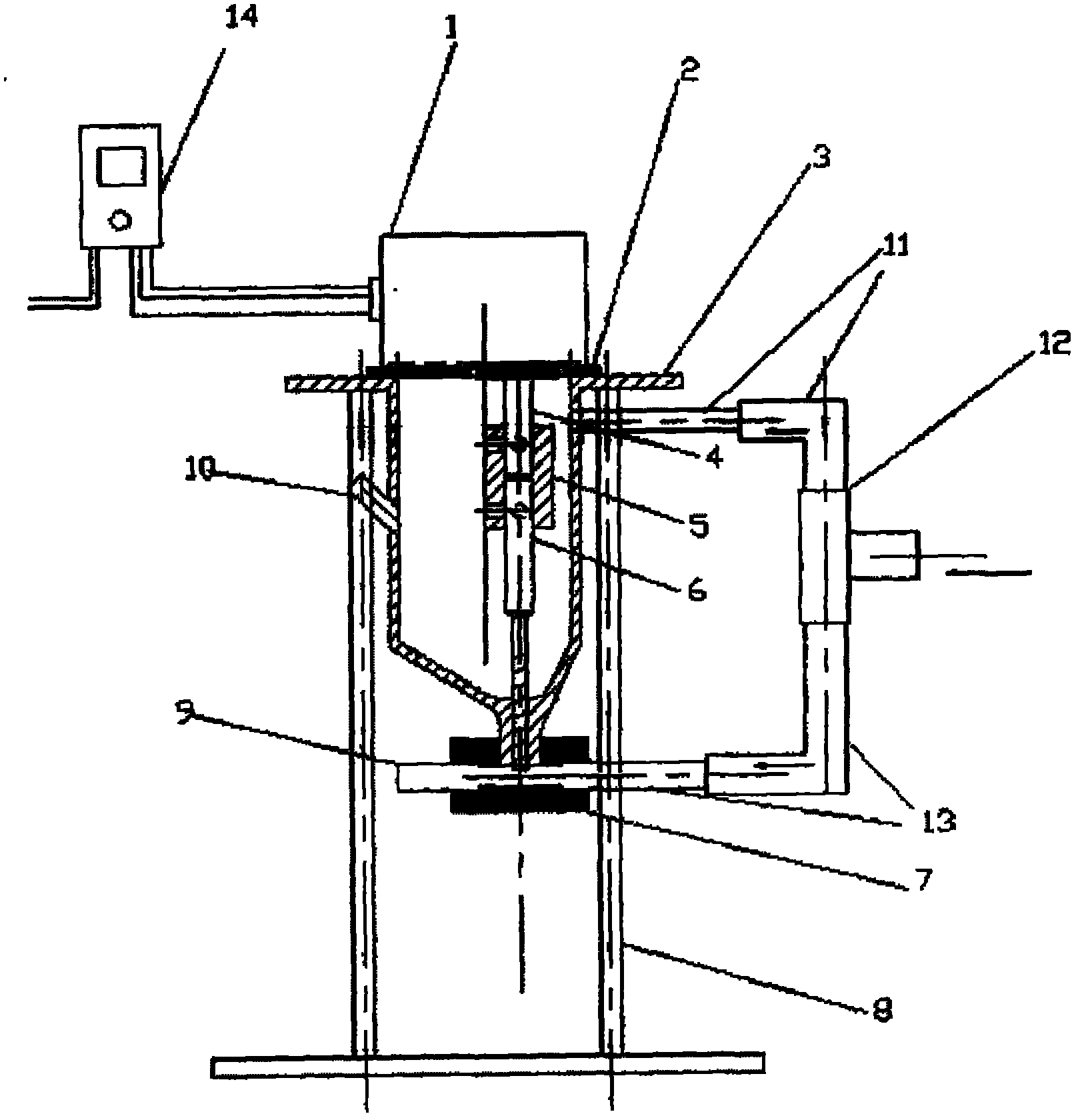
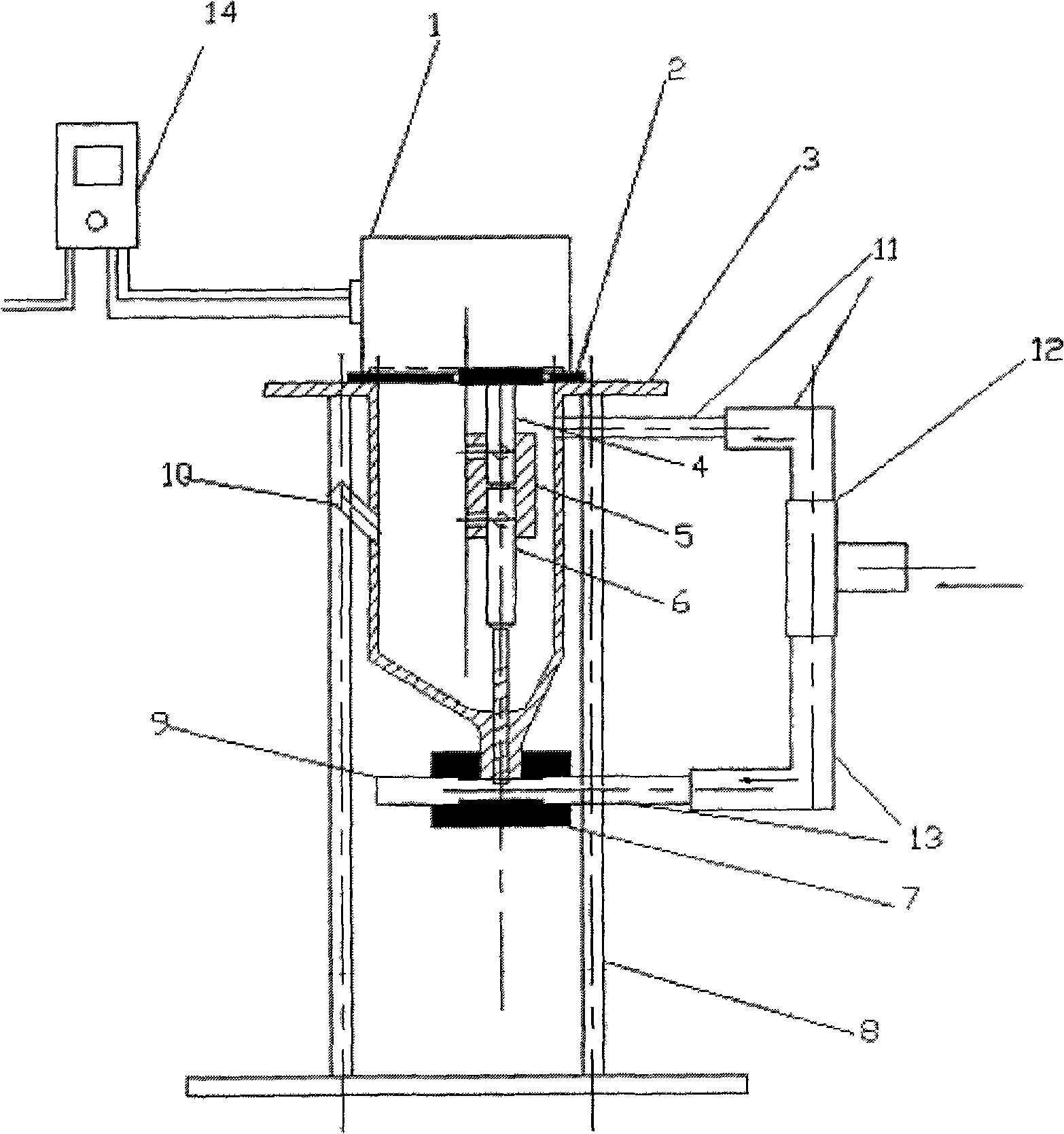
[0009] Such as figure 1 As shown, the present invention is a micro-controllable vertical screw powder feeder. The motor 1 is placed on the silo 3 and connected to the speed governor 14. The gasket 2 is placed between the motor 1 and the silo 3. The seat 8 is placed in the lower part of the silo 3, the coupling 5 is placed inside the silo 3, and connects the motor spindle 4 and the screw rod 6; the lower end of the screw rod 6 extends into the feeding tee 7, and the powder is transported to the feeder through its rotation. In the feeding tee 7; the feed pipe 10 is placed on one side of the wall of the silo 3; one end of the feeding tee 7 is connected to the lower part of the hopper 3, and the other two ends are respectively connected to the inlet pipe 13 and the discharge pipe 9; One end of the gas distribution tee 12 is connected to the pipeline of the gas cylinder, and the other two ends are respectively connected with the inlet pipe 13 and the balance air pipe 11, so that th...


PUM


Abstract

The invention discloses a vertical spiral powder conveyer. A motor (1) is arranged on a material cabin (3) and is connected with a speed adjuster (14); a sealing pad (2) is arranged between the motor (1) and the material cabin (3); a supporting seat (8) is arranged at the lower part of the material cabin (3); a shaft coupler (5) is arranged in the interior of the material cabin (3) and is connected with a motor spindle (4) and a spiral rod (6); the lower end of the spiral rod (6) extends into a material conveying tee joint (7), and the spiral rod is rotated to convey powders into the material conveying tee joint (7); a material inlet pipe (10) is arranged on one side of the wall of the material cabin (3); one end of the material conveying tee joint (7) is connected with the lower part of the material cabin (3), and the other two ends of the material conveying tee joint (7) are respectively connected with an air inlet pipe (13) and a material outlet pipe (9); one end of an air distribution tee joint (12) is connected with a pipeline of the air bottle, and the two other ends of the air distribution tee joint are respectively connected with the air inlet pipe (13) and a balance air pipe (11) for dividing air into two air paths; and the material outlet pipe (9) is connected with the material conveying tee joint (7) for outputting the powders from the powder conveyer.

Description

technical field [0001] The present invention relates to powder conveying machinery for spray coating. Background technique [0002] Small particle powder delivery technology has a wide range of applications in surface engineering fields such as welding, cladding and spraying. The types of powder feeders currently used mainly include screw type, rotary disk type and capillary type. Among them, the screw powder feeder can transport powder with a particle size greater than 15 μm, and the minimum diameter of the capillary powder feeder can reach 0.4 μm. When the powderer is conveying small particle powder, the continuity and uniformity of powder feeding are poor, and it is easy to cause blockage. However, in the case of micro-powder feeding, it is difficult for rotary disc and capillary powder feeders to realize continuous adjustment of powder feeding volume when transporting small particles and micro-powder. The traditional screw powder feeder is suitable for conveying small ...

Claims


Application Information

Patent Timeline
Patent Type & Authority Applications(China)
IPC IPC(8): B65G65/46B65G53/04
Inventor 黄勇李涛
Owner LANZHOU UNIVERSITY OF TECHNOLOGY
Why Eureka
Try Eureka