Movable wallboard-mounting carriage

A mobile, wall panel technology, applied in the direction of construction, building structure, building materials processing, etc., can solve the problems of difficult indoor transportation, high installation costs, high labor intensity, etc., to achieve simple and easy assembly and maintenance, and convenient operation , the effect of reducing labor intensity

Inactive Publication Date: 2012-08-08
周昌仁
View PDF6 Cites 5 Cited by
  • Summary
  • Abstract
  • Description
  • Claims
  • Application Information

AI Technical Summary

Problems solved by technology

[0002] In the known technology, various new building material partition wall panels often face the problem of difficulty in indoor transportation during installation. Sometimes the size of the wall panels can even reach more than 3 meters according to the frame structure conditions of the house. A 4.2-meter wall panel weighs about 300 kilograms. If The current manual handling and installation has to be carried by people on their shoulders. The installation requires 7 to 8 people. The damage rate is high, the labor intensity is high, the efficiency is low, the installation cost is high, and there are great safety hazards.
[0003] In the prior art, the use of auxiliary equipment to improve the technical disclosure of wall panel installation and transportation is less, such as patent application No. 201020100426 light-weight hollow partition wall panel electric installation forklift, on the flat surface of the forklift frame, the front end is equipped with lifting The track frame has a control cabinet at the rear end; a lifting device is installed on the lifting track frame, and a rotating device and a locking device used in conjunction with the rotating device are installed under the working table of the lifting device. The transition pulley and steel rope on the top of the lifting track frame are connected with the hoist; the reduction box of the hoist is connected with the motor located in the control cabinet

Method used


Image

  • Movable wallboard-mounting carriage
  • Movable wallboard-mounting carriage

Examples


Embodiment Construction

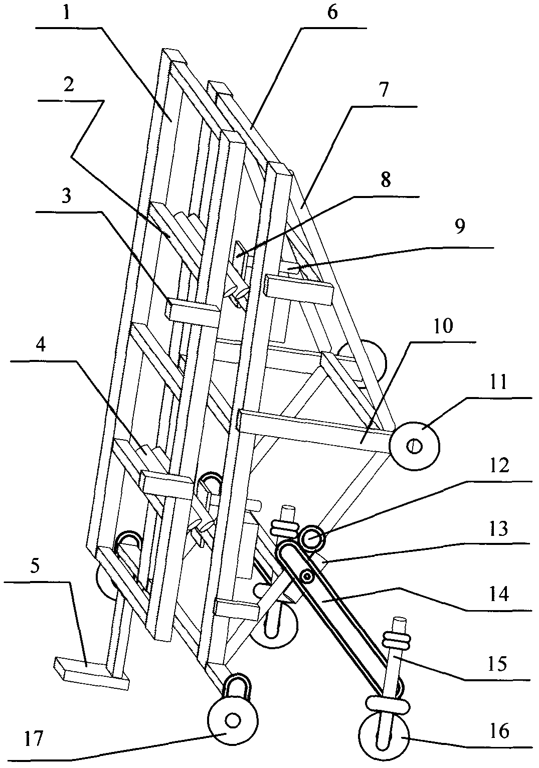
[0009] Further description will be given below in conjunction with the accompanying drawings and embodiments.

[0010] The rear side of the main frame 6 is installed with side wheels 11 through the support arm 10, the frame wheel 17 is installed at the lower end of the main frame 6, the front side of the main frame 6 is installed with the plate frame 1 through the hitch frame 4, the bottom of the plate frame 1 is connected with the bottom bracket arm 5, and the main frame 6. The plate frame 1 is installed by the hitch frame 4, and the live support leg 14 is hinged at the lower part of the rear side of the main frame 6, and the support wheel 16 is installed at the front end of the live support leg 14.

[0011] The plate frame 1 and the main frame 6 are rectangular frames, which are respectively composed of a pair of long frames on both sides and frame supports 2 connected between the frames.

[0012] A side stop 3 is installed on the side frame of the plate frame 1 . When the ...


PUM


Abstract

The invention relates to a movable wallboard-mounting carriage. Side wheels (11) are mounted on the back side of a main frame (6) through support arms (10), frame wheels (17) are mounted on the lower end of the main frame (6), a board frame (1) is mounted on the front side of the main frame (6) through hangers (4), the bottom of the board frame (1) is connected with a bottom holding arm (5), the board frame (1) is mounted on the main frame (6) through the hangers (4), movable support legs (14) are articulated with the lower part of the back side of the main frame (6), and support wheels (16) are mounted on the front ends of the movable support legs (14). Since the two sets of switching fulcrums in the form of the travelling wheels are arranged on the main frame, and the board frame and the main frame, the relative positions of which can be adjusted, are arranged, the movable wallboard-mounting carriage can assist manpower to conveniently carry out lifting, carrying, position adjustment and other mounting processes; and the movable wallboard-mounting carriage has a simple structure, is small in volume, is easy to assemble and repair and convenient to operate, the mounting speed is increased, decreases labor intensity, potential safety hazards are eliminated, and the zero-damage mounting of wallboards is realized, and the movable wallboard-mounting carriage is suitable for carrying, putting up and putting down partition battens indoors, and the evenness of a wallboard during mounting can be accurately adjusted, and the human resource can be greatly saved.

Description

technical field [0001] The invention relates to an auxiliary equipment technology or device for building construction in the international patent classification E04G, especially a mobile wall panel installation vehicle frame. Background technique [0002] In the known technology, various new building material partition wall panels often face the problem of difficulty in indoor transportation during installation. Sometimes the size of the wall panels can even reach more than 3 meters according to the frame structure conditions of the house. A 4.2-meter wall panel weighs about 300 kilograms. If The current manual handling and installation has to be carried by people on their shoulders. The installation requires 7 to 8 people. The damage rate is high, the labor intensity is high, the efficiency is low, the installation cost is high, and there is a great potential safety hazard. [0003] In the prior art, the use of auxiliary equipment to improve the technical disclosure of wall...

Claims


Application Information

Patent Timeline
IPC IPC(8): E04G21/16
Inventor 周昌仁
Owner 周昌仁
Why Eureka
Try Eureka