Vibration reduction device of rotating elements

A vibration damping device and technology of rotating parts, applied in the field of vibration damping devices, can solve the problems of high cost, matching, and long manufacturing cycle, and achieve the effects of saving processing costs, realizing vibration damping effect, and simple structure

Inactive Publication Date: 2012-08-08
GREAT WALL MOTOR CO LTD
View PDF4 Cites 3 Cited by
  • Summary
  • Abstract
  • Description
  • Claims
  • Application Information

AI Technical Summary

Problems solved by technology

At present, to solve this problem, it is more traditional to solve these problems through dual-mass flywheel or clutch plus multi-stage shock absorption, but these technologies are not only costly to implement, but also have a long matching and manufacturing cycle.

Method used


Image

  • Vibration reduction device of rotating elements
  • Vibration reduction device of rotating elements
  • Vibration reduction device of rotating elements

Examples


Embodiment 1

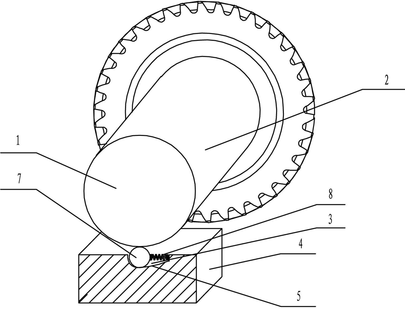
[0021] The vibration damping device for the rotating part of the present embodiment takes the gear as the rotating part 1 as an example. figure 1 As shown, the outer surface 2 is an end surface of the gear. The vibration damping device for rotating parts includes a housing 4 with a recessed part 3, and an embedded sleeve 9 is fixed in the recessed part 3 of the housing 4. The embedded sleeve 9 is a hollow cylindrical structure, and is embedded and fixed in the embedded sleeve 9. There is a guide part 6 with a guide surface 5. In this embodiment, the longitudinal section shape of the guide part 6 is a right-angled trapezoid. The inclined surface on the left side of the guide part is the guide surface 5. A rolling Body 7, rolling body 7 adopts ball, and the bottom of ball is provided with a spring 8 that is supported to ball, is fixedly connected with mosaic sleeve 9 inwalls, applies a supporting force to ball by spring 8, makes ball be in free state.

[0022] In use, when the ...

Embodiment 2

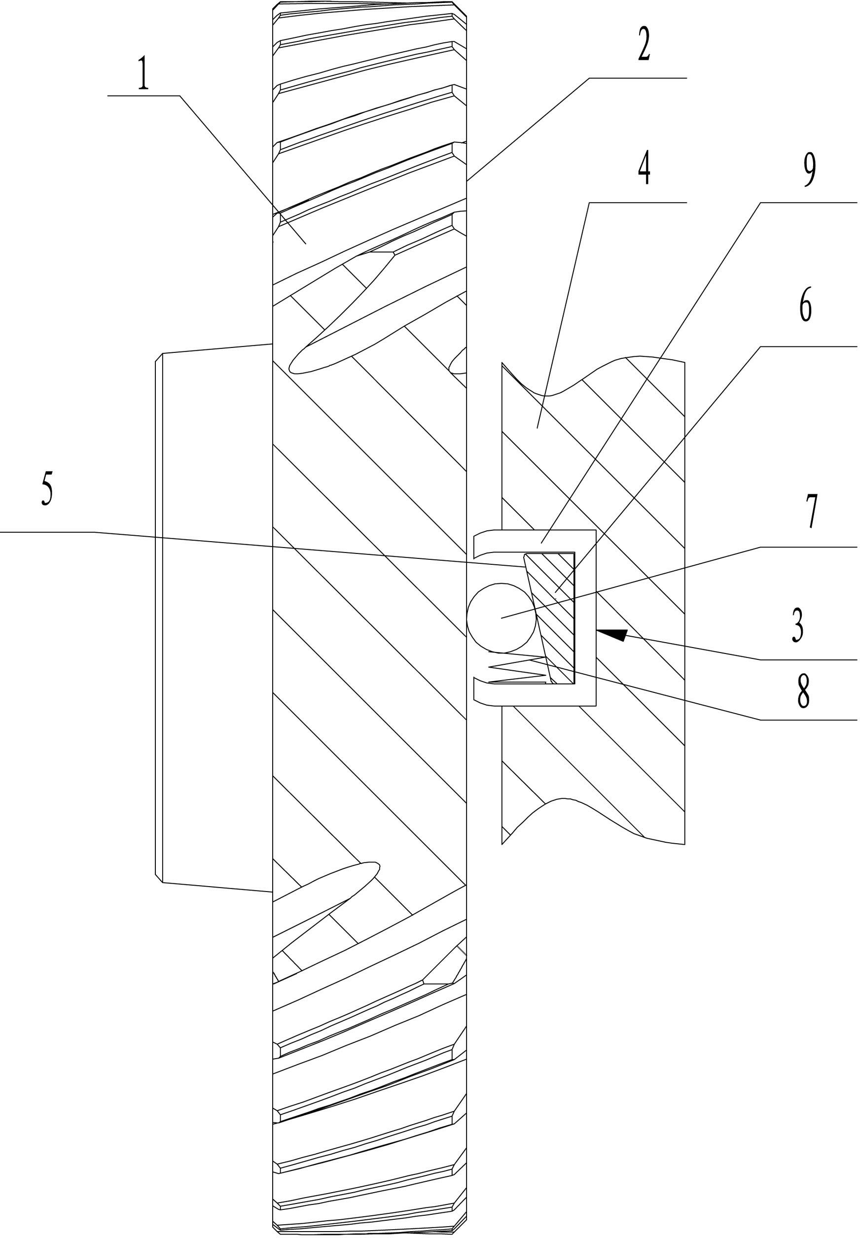
[0025] Depend on figure 2 It can be seen that the present embodiment takes the gear shaft as the rotating member 1 as an example. The vibration damping structure of the rotating member in this embodiment is basically the same as that of Embodiment 1, except that the inlay sleeve 9 is eliminated, and the recessed The bottom surface of the part 3 is used as the guide surface 5, and the guide surface 5 is designed as a curved surface, which makes the concave part 3 have a spatial structure that gradually becomes smaller from left to right. Depend on figure 2 It can be seen that when the gear shaft rotates clockwise normally, the gear shaft 1 drives the rolling body 7 to move to the left to a stable point, and the rolling body 7 above the stable point abuts against the gear shaft, and the rolling body 7 The bottom is in contact with the guide surface 5, and this contact point is the first position of the guide surface 5. When the gear shaft rotates abnormally, the rolling eleme...


PUM


Abstract

The invention relates to a device for reducing the vibration in the rotating process of rotating elements such as a gear or a gear shaft and the like in an automobile speed changer, in particular to a vibration reduction device of rotating elements. The vibration reduction device comprises a casing (4), a guide part (6) and a rolling body (7), wherein the casing (4) is provided with a sunk part (3), the guide part (6) is fixedly arranged in the sunk part (3) and is provided with a guide surface (5), the rolling body (7) is arranged between the guide surface (5) and the outer surface (2) in a rolling way, and a spring (8) for supporting the rolling body (7) is arranged on the casing (4). When the scheme is adopted, the vibration reduction effect is realized during the abnormal rotation of the rotating elements, the noise caused by the abnormal rotation is further reduced, and the structure is simple.

Description

technical field [0001] The invention relates to a device for damping vibration of rotating parts such as gears or gear shafts in an automobile transmission, in particular to a vibration damping device for rotating parts. Background technique [0002] At present, with the improvement of customers' driving sense and comfort requirements, the requirements for strong power and NVH characteristics are becoming more and more stringent, but large power input will bring large vibration sources, and often occur during the gear rotation meshing process or with When the gear shaft of the meshing gear rotates normally, it reverses instantaneously, which inevitably increases the torque vibration and speed fluctuation of the transmission. At the same time, it also brings the negative response of the transmission equipped, producing knocking sound and "click" sound , "click" sound or screaming sound, etc. At present, for this problem, it is more traditional to solve these problems through...

Claims


Application Information

Patent Timeline
IPC IPC(8): F16H57/028F16F15/02
Inventor 王克徐海山夏海军王传金杜新川孙月宾章金乐
Owner GREAT WALL MOTOR CO LTD
Why Eureka
Try Eureka