
Voltage sampling circuit

A technology of voltage sampling and voltage comparison circuit, which is applied in voltage/current isolation, measurement of current/voltage, measurement of electrical variables, etc., can solve the problems of large sampling error, influence on control accuracy, isolation of single-chip control signal and voltage sampling signal, etc. Achieve the effect of small sampling error, high control precision and avoid influence

Active Publication Date: 2012-08-08
东莞市精诚电能设备有限公司
View PDF5 Cites 45 Cited by
  • Summary
  • Abstract
  • Description
  • Claims
  • Application Information

AI Technical Summary

Problems solved by technology

[0003] In the existing voltage sampling circuit, the voltage division method is usually used for sampling, and the variables to be sampled are directly sampled. The control signal of the single-chip microcomputer is not effectively isolated from the voltage sampling signal, which affects the control accuracy and has sampling errors. bigger problem

Method used


Image

  • Voltage sampling circuit
  • Voltage sampling circuit

Examples


Embodiment Construction

[0012] In order to facilitate the understanding of those skilled in the art, the present invention will be further described in detail below in conjunction with the accompanying drawings and specific embodiments.

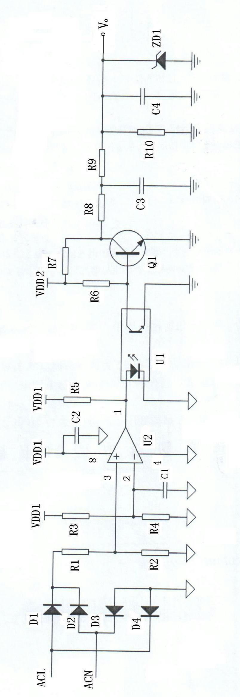
[0013] as attached figure 1 As shown, a voltage sampling circuit, the voltage sampling circuit includes a rectification circuit, a voltage comparison circuit, a photocoupler U1, a level conversion circuit and a smoothing filter circuit connected to each other in sequence.

[0014] The rectification circuit is composed of four diodes D1, D2, D3 and D4 to form a bridge rectification circuit.

[0015] The voltage comparison circuit includes a voltage comparator U2, a first resistor R1, a second resistor R2, a third resistor R3, a fourth resistor R4, a first capacitor C1, a second capacitor C1; one end of the first resistor R1 One end of the second resistor R2 is connected to the non-inverting input end of the voltage comparator U2, one end of the third resistor R3, on...


PUM


Abstract

The invention discloses a voltage sampling circuit, which comprises a rectifying circuit, a voltage comparison circuit, a photoelectric coupler, a level switching circuit and a smooth filtering circuit, wherein the same-phase input end of the voltage comparison circuit is connected with the anode of the output end of the rectifying circuit through a resistor; an anode pin at the signal input end of the photoelectric coupler is connected with the signal output end of the voltage comparison circuit; a collector pin at the output end of the photoelectric coupler is connected with the signal input end of the level switching circuit; and the signal input end of the smooth filtering circuit is connected with the signal output end of the level switching circuit. According to the voltage sampling circuit, isolated sampling is realized through the photoelectric coupler, a control signal is isolated from a sampling signal, and the influence of an outer voltage power grid on the control signal is effectively avoided; and the voltage sampling circuit has the advantages of high control precision, small sampling error and the like.

Description

technical field [0001] The invention relates to a sampling circuit, in particular to a voltage sampling circuit. Background technique [0002] In the circuit board of household appliances, in order to prevent large fluctuations in grid voltage from causing damage to electrical appliances, a voltage sampling circuit is usually set up, and the signal obtained by the voltage sampling circuit is sent to the microcontroller for processing. When the grid voltage is detected to be greater than When a certain value or less than a certain value, the control circuit related to the single-chip microcomputer will control the electrical appliances to stop working, so as not to cause damage to them. For example, the voltage sampling circuit in the induction cooker sends the signal obtained by sampling the grid voltage to the single-chip microcomputer for processing. When the induction cooker is working, the single-chip microcomputer detects the change of the voltage sampling signal at all...

Claims


Application Information

Patent Timeline
Patent Type & Authority Applications(China)
IPC IPC(8): G01R19/165G01R15/22
Inventor 梁树清周杰
Owner 东莞市精诚电能设备有限公司
Learn More