Method and device for tracing maximum power point and power supply system

A technology of maximum power point and power supply system, applied in the direction of control/regulation system, photovoltaic power generation, electrical components, etc., can solve the problems of long adjustment time, low response speed, difficult maximum power output, etc., to reduce the number of measurements and reduce adjustments The effect of increasing the number of times and improving the overall response speed

Active Publication Date: 2014-12-17
HUAWEI DIGITAL POWER TECH CO LTD
View PDF4 Cites 0 Cited by
  • Summary
  • Abstract
  • Description
  • Claims
  • Application Information

AI Technical Summary

Problems solved by technology

[0005] Embodiments of the present invention provide a maximum power point tracking method, device, and power supply system to solve the problems of low response speed of the power supply system, long adjustment time, and difficulty in quickly achieving maximum power output during maximum power point tracking.

Method used


Image

  • Method and device for tracing maximum power point and power supply system
  • Method and device for tracing maximum power point and power supply system
  • Method and device for tracing maximum power point and power supply system

Examples


no. 1 example

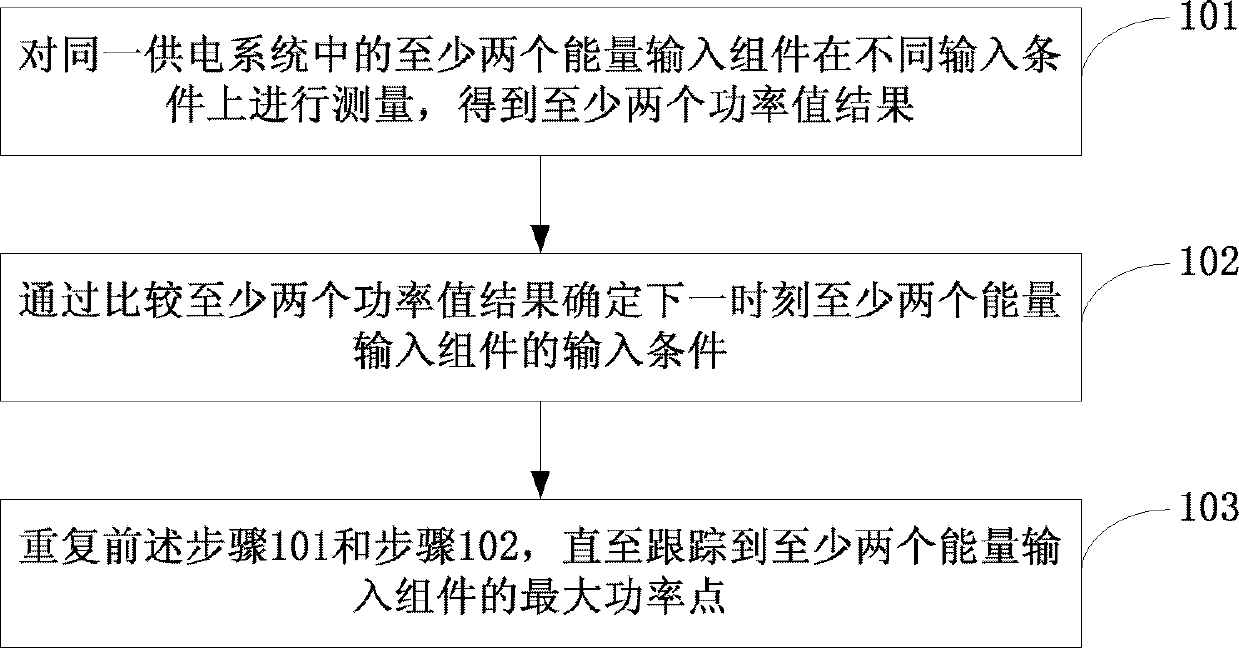
[0034] See figure 1 , Is a flowchart of the first embodiment of the maximum power point tracking method of the present invention:

[0035] Step 101: Measure at least two energy input components in the same power supply system under different input conditions to obtain at least two power value results.

[0036] In the embodiment of the present invention, the power supply system may be a solar photovoltaic power generation system, which uses solar photovoltaic panels as an energy input component, or a wind power generation system which uses wind turbine blades as an energy input component. Different from the prior art that uses serial mode to scan power points, the embodiment of the present invention measures at least two energy input components on different input conditions at the same time, so that by comparing the results of each measurement, a parallel scan method is used to determine the next Input conditions of at least two energy input components at a time.

[0037] In this emb...

no. 1 example

[0061] See image 3 , Is a block diagram of the first embodiment of the maximum power point tracking device of the present invention:

[0062] The device includes a measuring unit 310, a determining unit 320, and a tracking unit 330.

[0063] Wherein, the measuring unit 310 is configured to measure at least two energy input components in the same power supply system under different input conditions to obtain at least two power value results;

[0064] The determining unit 320 is configured to determine the input conditions of the at least two energy input components at the next moment by comparing the results of the at least two power values;

[0065] The tracking unit 330 is configured to repeatedly execute the functions of the aforementioned measuring unit 310 and the determining unit 320 until the maximum power point of the at least two energy input components is tracked.

no. 2 example

[0066] See Figure 4A , Is a block diagram of the second embodiment of the maximum power point tracking device of the present invention:

[0067] The device includes: a measurement unit 410, a determination unit 420, a tracking unit 430, and an adjustment unit 440.

[0068] Wherein, the scanning unit 410 is configured to measure at least two energy input components in the same power supply system under different input conditions to obtain at least two power value results;

[0069] The determining unit 420 is configured to determine the input conditions of the at least two energy input components at the next moment by comparing the results of the at least two power values;

[0070] The tracking unit 430 is configured to repeatedly perform the functions of the aforementioned measuring unit 410 and the determining unit 420 until the maximum power point of the at least two energy input components is tracked;

[0071] The adjusting unit 440 adjusts the power of other energy input components ...


PUM


Abstract

An embodiment of the invention discloses a method and a device for tracing a maximum power point and a power supply system. The method comprises the steps of: measuring at least two energy input modules of the same power supply system under different input conditions to obtain at least results of two power values; determining input conditions of the at least two energy input modules for the next moment through the comparison of the results of the two power values; and repeating the above steps until the maximum power point of the at least two energy input modules is traced; In the embodiment of the invention, the maximum power point can be traced in parallel among different energy modules, thereby adjusting times of the input conditions can be reduced; and measuring times of every energy input module under different input conditions can be reduced, thereby an overall response speed of the power supply system can be improved when the maximum power point is being traced; adjusting time can be reduced; a maximum power output of the power supply system can be realized rapidly; and the system generating capacity can be raised.

Description

Technical field [0001] The invention relates to the technical field of new energy power generation, in particular to a maximum power point tracking method, device and power supply system. Background technique [0002] In the process of developing new energy, solar photovoltaic power generation and wind power generation are widely used. Take the solar photovoltaic power generation system as an example. The system traces the direction of the sun through solar panels, so that the sun's rays can always illuminate the solar panels vertically to maximize photovoltaic power generation. The output characteristics of the solar panel are greatly affected by external environmental factors such as light intensity and temperature, so its output power has time-varying nonlinear characteristics. It is necessary to change the output voltage or current or tilt angle of the solar panel to make it work at the best power. On the curve. [0003] A solar power generation system in the prior art usuall...

Claims


Application Information

Patent Timeline
Patent Type & Authority Patents(China)
IPC IPC(8): G05F1/67H02S40/30
CPCY02E10/50
Inventor 石勇陶渊郭新
Owner HUAWEI DIGITAL POWER TECH CO LTD
Why Eureka
Try Eureka