elastic sole

A technology of elastic and hollow parts, applied in soles, footwear, applications, etc., can solve the problems of insufficient elasticity and poor thermal insulation performance, and achieve the effect of prolonging the thermal insulation time

A technology of elastic and hollow parts, applied in soles, footwear, applications, etc., can solve the problems of insufficient elasticity and poor thermal insulation performance, and achieve the effect of prolonging the thermal insulation time

CN102631048BInactive Publication Date: 2015-11-18ηŽ‹ζΈ…ηŸ³ +1

Image

  • elastic sole
  • elastic sole

Examples


Embodiment Construction

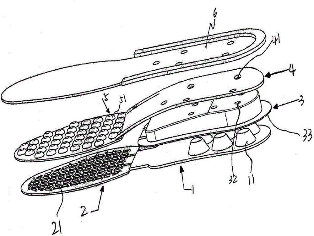
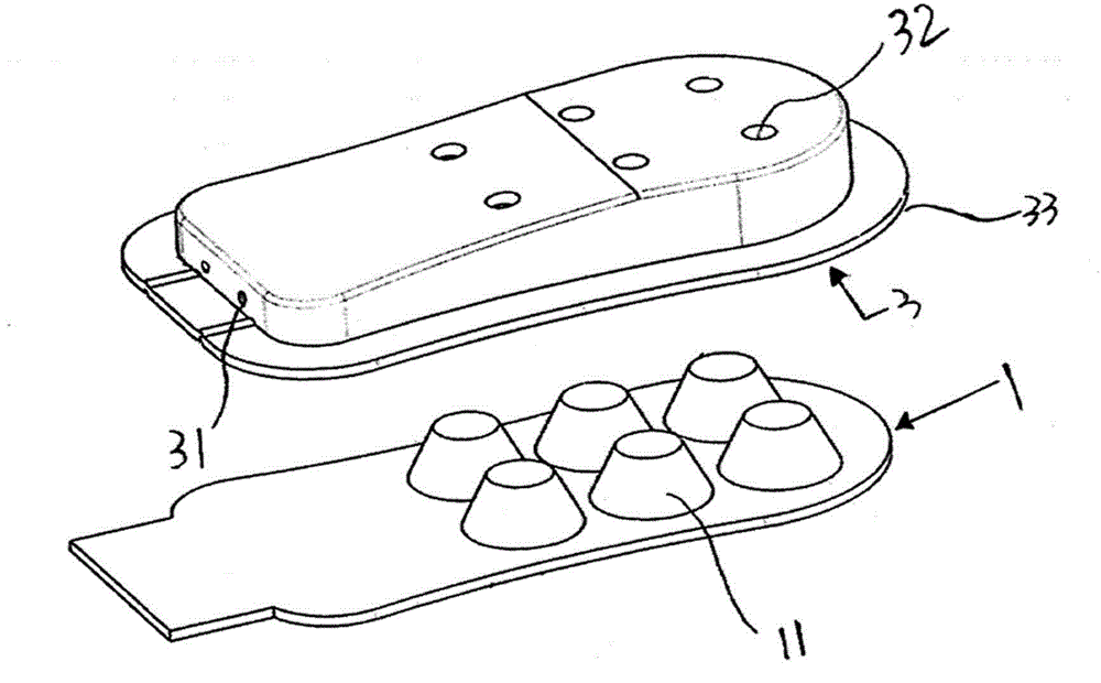
[0013] see figure 1 and figure 2 , these two drawings provide the appearance structure of an embodiment of the elastic sole proposed by the present invention. The elastic sole comprises a back pad 1, a front pad 2, an elastic hollow part 3 and a pressure-bearing plate 4 arranged in sequence above the back pad 1, a buffer pad 5 is arranged above the front pad 2, and a pressure-bearing plate 4 And the top of the buffer pad 5 is provided with a spacer 6 .

[0014] The rear pad 1, the elastic hollow member 3 and the front pad 2 are all made of elastic materials, such as rubber. Wherein, the tarsus region of the rear pad 1 is provided with six elastic protrusions 11 extending upwards to increase the elasticity of the rear pad 1 . Since the elastic boss 11 mainly plays the role of increasing the elasticity of the sole, the elastic boss 11 can adopt different structures and quantities, for example, 1-5 elastic bosses 11 can be arranged, and the structure can adopt a hollow surfac...


PUM


Abstract

The invention relates to an elastic sole. An elastic convex column, an elastic hollow piece and a bearing plate piece are arranged in a tarsal region of a rear pad of the sole, wherein the elastic convex column upwards extends, the elastic hollow piece is arranged above the rear pad of the sole and allows the elastic convex column to enter, the bearing plate piece is arranged above the elastic hollow piece, and transverse air holes are formed in the elastic hollow piece along the direction towards a front pad. When the elastic hollow piece in the elastic sole is extruded by an outer force and freely pops up, air in the elastic hollow piece flows through the transverse air holes; due to the ventilation action, the interior part of the shoe can be kept dry, and the heat preservation time of the sole can be prolonged; and functions of warming in winter and cooling in summer are realized.

Description

technical field [0001] The invention relates to an elastic shoe sole. Background technique [0002] Wearing shoes for walking or exercising not only protects one's feet from injury, but also acts as a shock absorber. When people are walking or exercising, the reason for the vibration to the human body is mainly from the soles of the shoes. Therefore, to reduce or avoid the vibration force generated by the human body, the only solution is to increase the elasticity of the soles. For this reason, in the prior art, usually adopt rubber or ethylene-vinyl acetate copolymer as the raw material of making shoe sole, to improve the flexibility and impact resistance of shoe sole. However, the sole is a component that is in direct contact with the ground and bears the weight of the human body. In general, the flexibility or elasticity and impact resistance of the sole are contradictory, that is, the better the flexibility, the worse the impact resistance. The better the flexibility o...

Claims


Application Information

Patent Timeline
18 Nov 2015
Publication
CN102631048B
IPC
A43B13/18
Inventors
ηŽ‹ζΈ…ηŸ³; ηŽ‹ζ’