Reversing radar sensing assembly

A sensor component, reversing radar technology, applied in vehicle parts, instruments, radio wave measurement systems, etc., can solve the problems of affecting detection accuracy, damage, and the sensor assembly structure cannot be installed on the bumper, to ensure accuracy and performance. Stable and controllable installation accuracy

Active Publication Date: 2014-03-26
STEELMATE CO LTD
View PDF7 Cites 1 Cited by
  • Summary
  • Abstract
  • Description
  • Claims
  • Application Information

AI Technical Summary

Problems solved by technology

[0008] First of all, due to the solidified thinking of the sensor installation structure, in the existing technology, it is still customary to expose the sensor to the car bumper, so that it is easier to be damaged by impact, and the sensor still cannot effectively prevent the damage caused by violent vibration.
[0009] Secondly, and most importantly, different car bumpers have different thicknesses. The sensor assembly structure disclosed above and the entire prior art also adopt similar assembly structures. These assembly structures all assume that the car bumper has a constant thickness. Therefore, for thicker guard bars, unless a sensor assembly structure is produced to accommodate the corresponding wall thickness, such sensor assembly structures will not be able to be installed on thicker guard bars
[0010] Furthermore, the installation of the reversing radar sensor has a certain angle requirement. By marking the up and down directions on the sensor to assist the installer to align the installation orientation of the sensor, it is not arbitrarily designated, otherwise it will affect its detection accuracy.
In the prior art, holes are first drilled on the guard bar, and then the sensor is snapped into the guard bar to realize installation. This rigid installation method is not easy to grasp the installation angle of the sensor
[0011] The above analysis shows that the installation structure of the sensor in the prior art has a large room for improvement.

Method used


Image

  • Reversing radar sensing assembly
  • Reversing radar sensing assembly
  • Reversing radar sensing assembly

Examples


Embodiment Construction

[0029] Below in conjunction with accompanying drawing and embodiment the present invention will be further described:

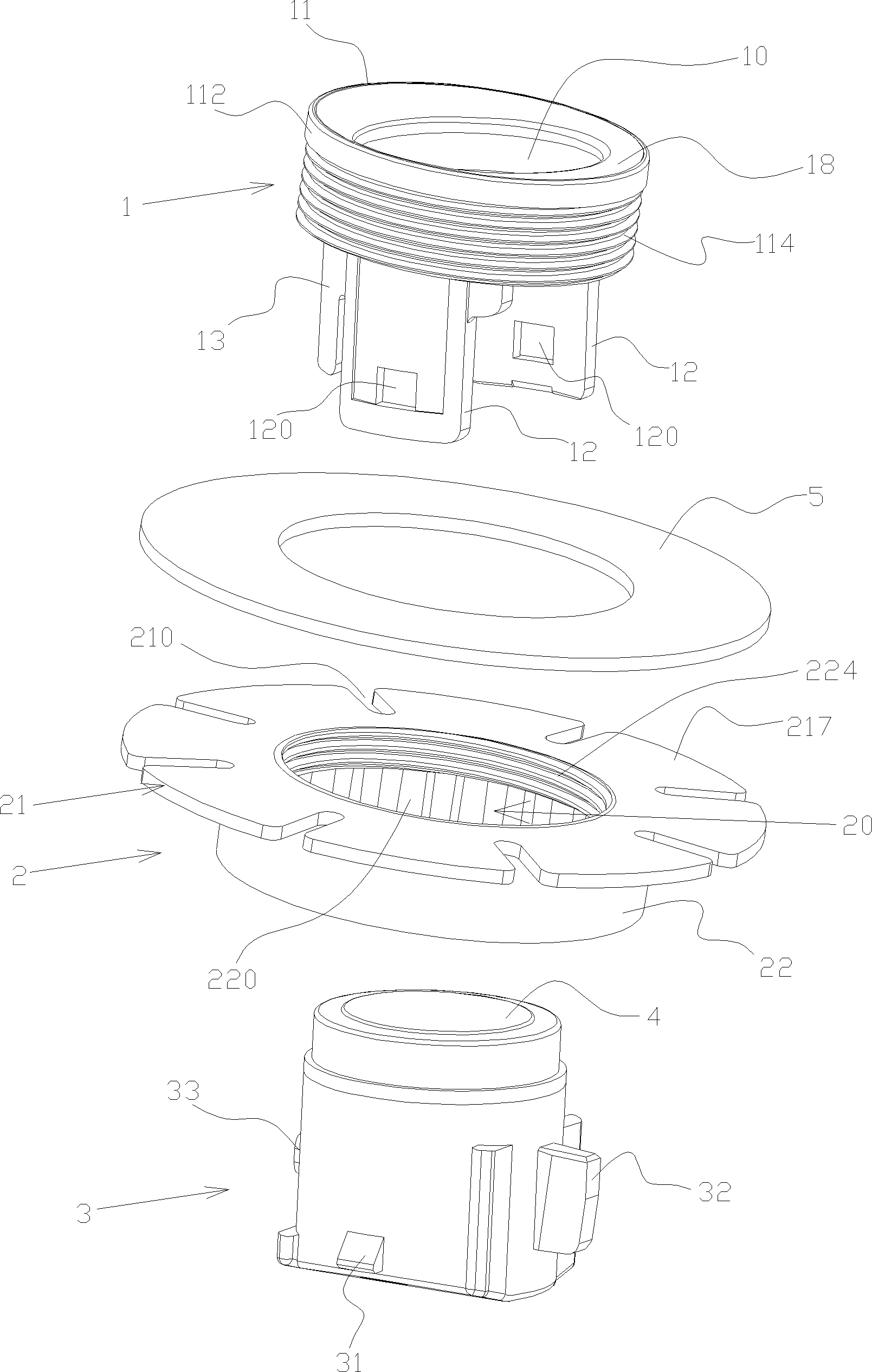
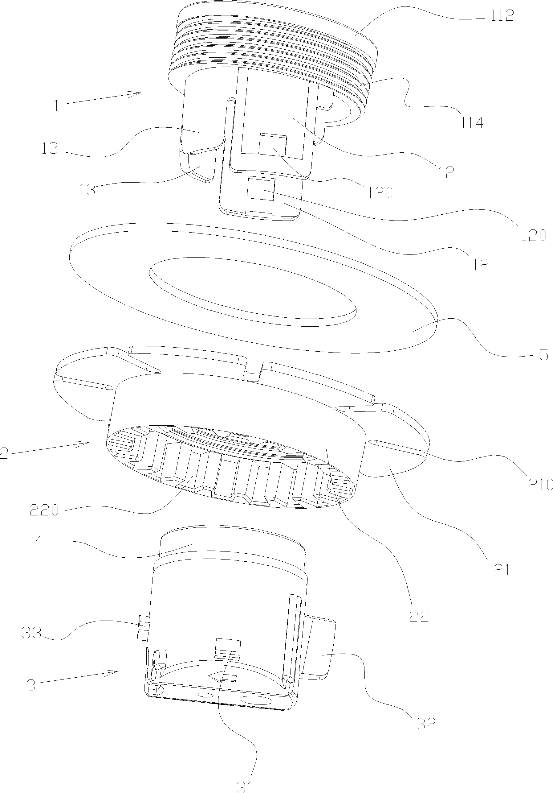
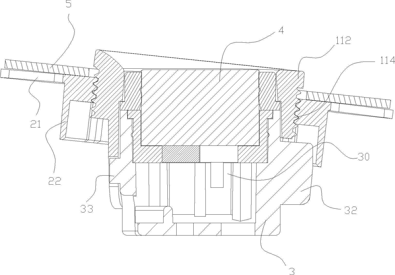
[0030] The reversing radar sensing assembly of the present invention, as a necessary component of the car reversing radar system, is often installed in the preset through hole on the rear bumper or similar front-end parts of the car, and can also be installed in other directions of the car. For example, in the through-holes preset on the side or forward guard bars or similar front parts, so that the distance between these cars and the roadblocks in this direction is initially sensed. A plurality of through holes are usually provided on the bumper or similar front-end parts on the same side of the car, so that a plurality of reversing radar sensor assemblies of the present invention are installed correspondingly, and a central control unit is arranged inside the car, and the central control unit collects various Set the signal detected by the sensing component...


PUM


Abstract

The invention discloses a reversing radar sensing assembly, comprising a sensor. The reversing radar sensing assembly further comprises a cover cap, an adjusting piece and a base, wherein the cover cap is placed into a pre-set through hole of an automobile retaining bar as a front end and comprises a cylindrical cover provided with an axial through hole and an extending piece arranged at one side of the cylindrical cover; the adjusting piece comprises a cylindrical part provided with the axial through hole and a sheet-shaped part which radially expands from one end of the cylindrical part and is fixedly connected with the automobile retaining bar; the base is provided with a containing space for assembling a sensor; the cylindrical cover of the cover cap is sleeved by the adjusting piece through the cylindrical part; the base is arranged in the cylindrical cover of the cover cap by using the sensor as the front end and the base and the extending part of the cover cap and the base and the cylindrical part of the adjusting piece are respectively fixed. The reversing radar sensing assembly provided by the invention can be suitable for the automobile retaining bars with different thicknesses so as to realize hidden type installation. Furthermore, the reversing radar sensing assembly is simple in structure, stable in connection and easy to install.

Description

【Technical field】 [0001] The invention relates to the installation technology of a car reversing radar, in particular to a reversing radar sensor assembly. 【Background technique】 [0002] The sensors used in the reversing radar system are usually arranged in a line on the rear bumper of the car to transmit ultrasonic signals to the rear of the car for distance detection. The installation structures of these sensors are varied, but they remain the same. [0003] Please refer to patent announcement CN2929296, which discloses a fixing device for a reversing radar sensor. The reversing radar disclosed in this patent announcement represents most of the structures in the industry, so it is representative to a certain extent. [0004] It can be seen from the description and accompanying drawings of the above-mentioned technical solution that the reversing radar sensor is inserted into the hollow head cover, and a shock-absorbing pad is used on the periphery to protect the sensor, ...

Claims


Application Information

Patent Timeline
Patent Type & Authority Patents(China)
IPC IPC(8): B60R11/00G01S7/02
Inventor 李植滔
Owner STEELMATE CO LTD
Why Eureka
Try Eureka