Machine vision detection device and method based on line scanning camera

A technology of machine vision inspection and line scan camera, which is applied in the direction of measuring devices, instruments, scientific instruments, etc., can solve the problems that the encoder cannot be found directly, high cost, etc., and achieve the effect of simple structure and low cost

Active Publication Date: 2012-08-15
ZHONG CHAO GREAT WALL FINANCIAL EQUIP HLDGCO +1
View PDF5 Cites 4 Cited by
  • Summary
  • Abstract
  • Description
  • Claims
  • Application Information

AI Technical Summary

Problems solved by technology

According to the resolution requirements of the image collected by the line scan camera, it is necessary to select an encoder with the corresponding resolution according to the diameter of the roller to trigger the line scan camera to take pictures of the printed matter to be detected, but sometimes the diameter of the active roller is not our ideal diameter, so For direct installation, an encoder with a very special resolution (such as a very high resolution requirement) is required, which cannot be found directly in the market, or even if it can be found, it will require a higher cost

Method used


Image

  • Machine vision detection device and method based on line scanning camera
  • Machine vision detection device and method based on line scanning camera
  • Machine vision detection device and method based on line scanning camera

Examples


Embodiment Construction

[0028] Embodiments of the present invention will be described in detail below in conjunction with the accompanying drawings.

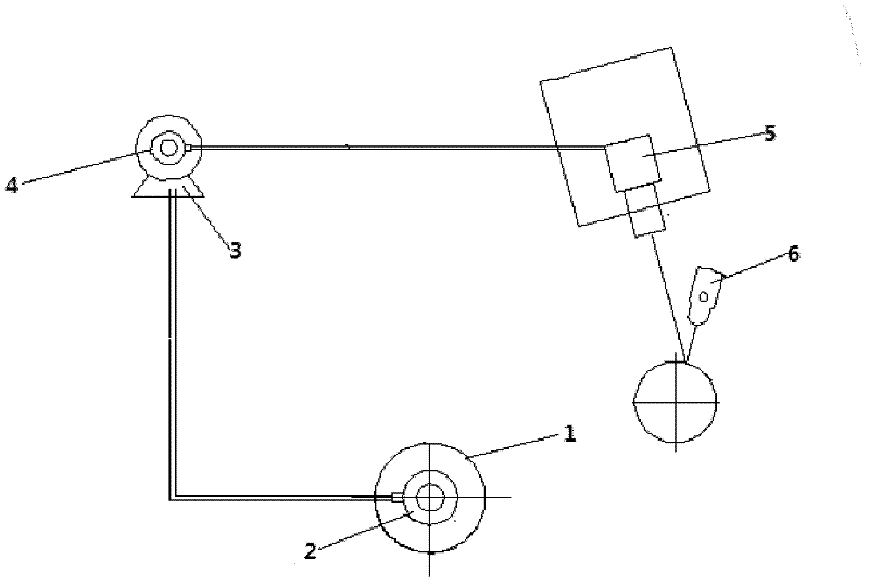
[0029] Such as figure 1 Shown is a schematic structural view of an embodiment of a machine vision inspection device based on a line scan camera.

[0030] The machine vision inspection device includes a driving roller 1, a first encoder 2 and a line scan camera 5, wherein the product to be detected is placed on the surface of the driving roller 1, the first encoder 2 is installed on the driving roller 1, and the driving roller The cylinder 1 drives the first encoder 2 to generate the first encoder pulse signal by rotating, the diameter of the driving roller 1 is d, and the resolution of the first encoder 2 is K 1 , the resolution of the image collected by the line scan camera 5 is λ, and the encoder resolution required to trigger the line scan camera 5 to collect images is K, When the pulse signal of the first encoder does not meet the resolution req...


PUM


Abstract

The invention provides a machine vision detection device and method based on a line scanning camera. The machine vision detection device comprises a driving roller, a first encoder and the line scanning camera, wherein the first encoder is mounted on the driving roller which rotates to drive the first encoder to generate a first encoder pulse signal; the resolution of the first encoder is K1; the encoder resolution needed to trigger the line scanning camera to capture mages is K; when the first encoder pulse signal does not meet a requirement of the resolution needed to trigger the line scanning camera to capture images, the detection device further comprises a servo motor and a second encoder; the resolution of the second encoder is K2, wherein the second encoder is mounted on the servo motor; the first encoder pulse signal triggers the servo motor to rotate; a servo motor controller enables the rotation speed ratio of the servo motor and the driving roller to be alpha, wherein alpha is equal to K1*K2 / K; and the servo motor rotates to drive the second encoder to generate a second encoder pulse signal. Compared with the prior art, the machine vision detection device provided by the invention can meet the resolution requirement for triggering the line scanning camera to capture images by using existing ordinary encoders on the market, and has advantages of simple structure and low cost.

Description

technical field [0001] The invention relates to the field of machine vision detection, in particular to a line scan camera-based machine vision detection device and method. Background technique [0002] In practical industrial applications, a machine vision detection device with a line scan camera installed on a printing machine as an electronic eye is usually used to detect the printing quality of printed matter on-line. The typical structure of the machine vision inspection device is that the shooting position of the line scan camera is set on the generatrix of the roller, and the encoder is installed on the driving roller. According to the resolution requirements of the image collected by the line scan camera, it is necessary to select an encoder with the corresponding resolution according to the diameter of the roller to trigger the line scan camera to take pictures of the printed matter to be detected, but sometimes the diameter of the active roller is not our ideal dia...

Claims


Application Information

Patent Timeline
Patent Type & Authority Applications(China)
IPC IPC(8): G01N21/17
Inventor 张绍兵廖世鹏陈斌张元成苗
Owner ZHONG CHAO GREAT WALL FINANCIAL EQUIP HLDGCO
Why Eureka
Try Eureka