Gas sensor
A gas sensor and external gas technology, applied in instruments, scientific instruments, measuring devices, etc., can solve the problems of inability to miniaturize and large structure of the gas sensor, and achieve the effect of fewer structural parts, fewer process steps, and simpler assembly.
- Summary
- Abstract
- Description
- Claims
- Application Information
AI Technical Summary
Problems solved by technology
Method used
Image

Examples
Embodiment Construction
[0030] The present invention will be further described below in conjunction with specific embodiments and accompanying drawings, but the protection scope of the present invention should not be limited thereby.
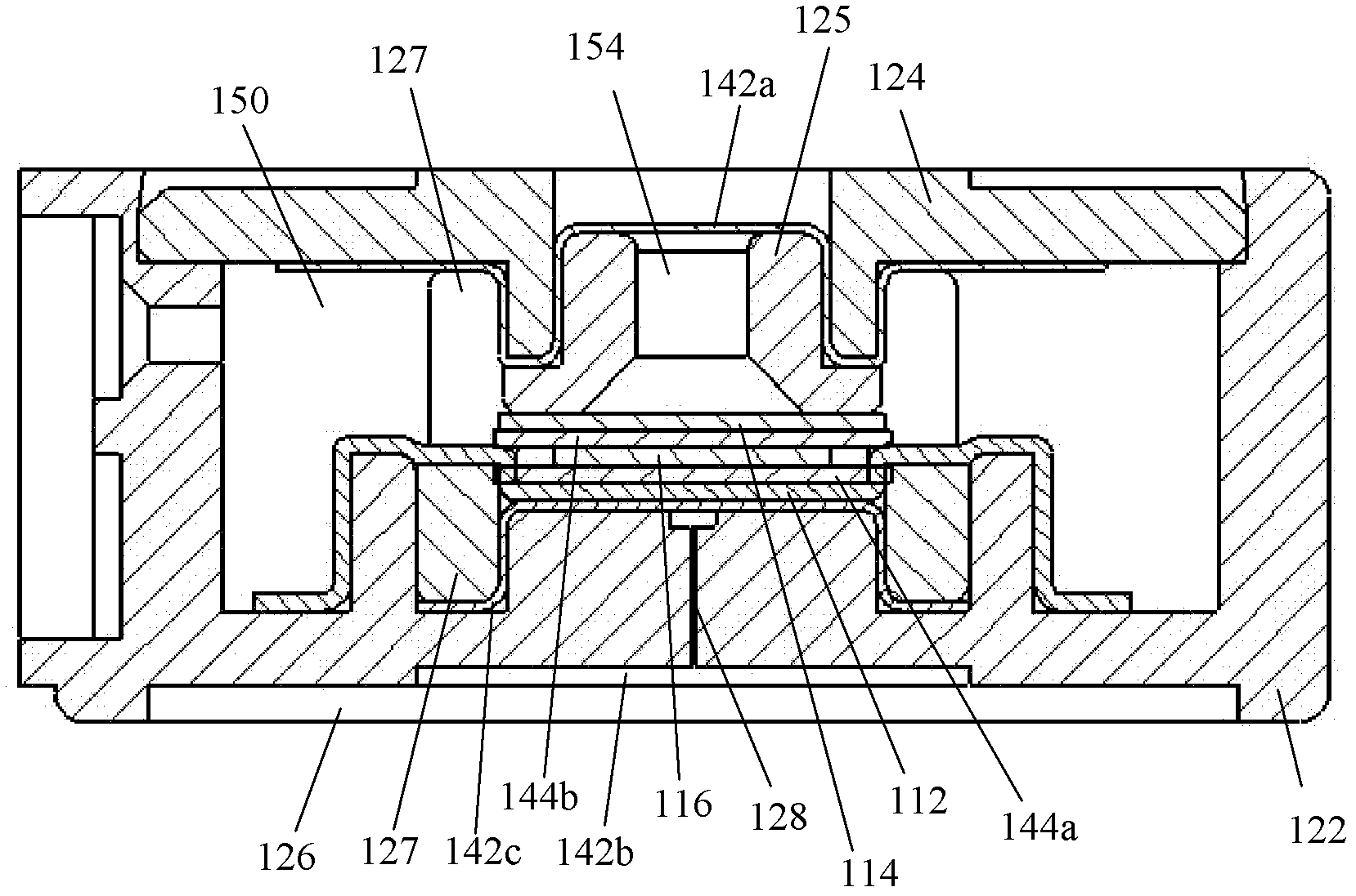
[0031] figure 1 A cross-sectional structure diagram of the gas sensor of this embodiment is shown, the gas sensor mainly includes: a housing 122, a housing cover 124, a bracket 127, a plug 125, a measuring electrode 112, a first liquid-absorbing material layer 144a, and a counter electrode 114, In addition, it also includes a second liquid-absorbing material layer 144b, a reference electrode 116, a first breathable and waterproof membrane 142a, a second breathable and waterproof membrane 142b, a dustproof membrane 126, and a third breathable and waterproof membrane 142c.
[0032] Wherein, the material of the housing 122 , the housing cover 124 , the bracket 127 and the plug 125 can be plastic. The outer shape of the housing 122 is cylindrical or nearly cylindrical. Th...
PUM
 Abstract
Description
Claims
Application Information