Supercharge Your Innovation With Domain-Expert AI Agents!

Ferrule with alignment pin channels

A technology for aligning pins and channels, applied in the field of MT sleeves, can solve problems such as performance degradation, and achieve the effect of simplifying the molding process

Inactive Publication Date: 2012-08-15
TYCO ELECTRONICS NETHERLAND BV
View PDF4 Cites 2 Cited by
  • Summary
  • Abstract
  • Description
  • Claims
  • Application Information

AI Technical Summary

Problems solved by technology

For example, a specific optical coupling in a mated single-mode MT ferrule may be satisfactory in one situation, however its performance may degrade considerably when the ferrule is re-mated

Method used


Image

  • Ferrule with alignment pin channels
  • Ferrule with alignment pin channels
  • Ferrule with alignment pin channels

Examples


Embodiment Construction

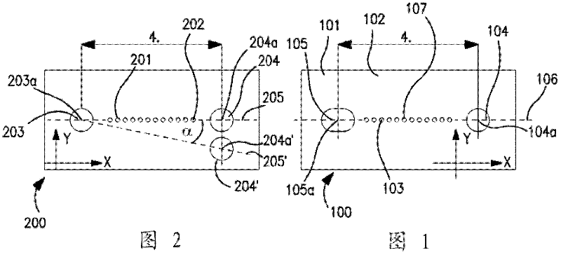
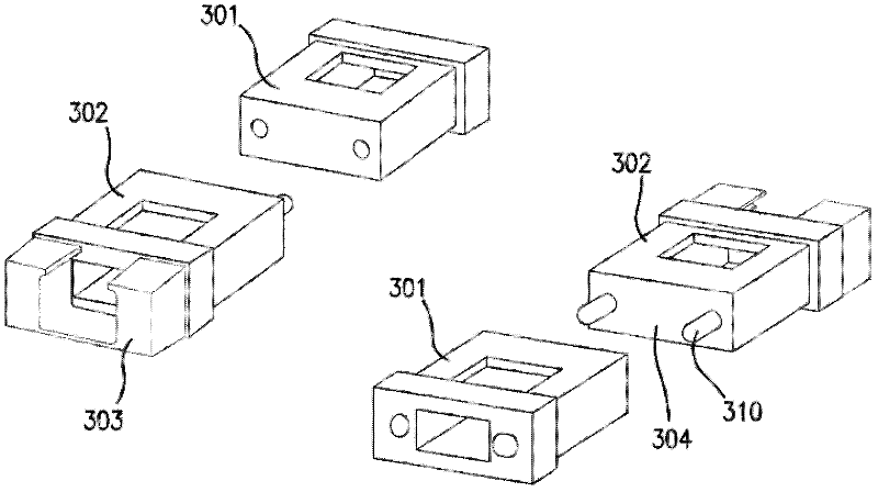
[0020] refer to figure 1 , shows an embodiment of the sleeve 100 of the present invention. The bushing 100 includes a body 101 defining an end face 102 . One or more channels 103 extend from the end face 102 through the body 101 . Each channel 103 is adapted to receive an optical fiber (not shown). The ferrule body also defines first and second alignment pin channels 104,105. Each alignment pin channel has a center point 104a, 105a disposed along a first axis 106 (dashed line). The first alignment pin channel 104 has an alignment pin 310 (see image 3 ) is substantially the same cross-section as the first cross-section and is adapted to receive an alignment pin. The second alignment pin channel 105 has a second cross-section elongated along the first axis 106 . Each element is considered in detail below and with respect to alternative embodiments.

[0021] The main body 101 of the ferrule is used to define a fiber optic channel 103 and alignment pin channels 104, 105, ...


PUM


Abstract

An optical ferrule includes: (a) a body (101) defining an end face (102); (b) one or more channels (103) extending from said end face through said body, each channel adapted to receive an optical fiber; and (c) first and second alignment pin channels (104,105) defined in said end face, each alignment pin channel having a center point, said center points being disposed along a first axis (106), said first alignment pin channel having a first cross section essentially the same as that of an alignment pin and being adapted to receive said alignment pin, said second alignment pin channel having a second cross section elongated along said first axis.

Description

technical field [0001] The present invention relates generally to a ferrule for an optical connector, and more particularly to an MT ferrule. Background technique [0002] Fiber optic connectors are an essential part of almost all fiber optic communication systems. For example, such connectors are used to join together segments of optical fiber, to connect optical fiber to active devices such as radiation sources, detectors, and repeaters, and to connect optical fiber to devices such as switches, multiplexers, etc. Passive devices for multiplexers and attenuators. [0003] A typical fiber optic connector includes a housing and a ferrule assembly within the housing. The ferrule assembly includes a ferrule having one or more fiber optic channels accommodating optical fibers, and an optical fiber secured in each channel, wherein the ends of the fibers are presented for optical coupling through the ferrule. The housing is designed to engage a "mating structure" having an opti...

Claims


Application Information

Patent Timeline
Patent Type & Authority Applications(China)
IPC IPC(8): G02B6/38G02B6/36
CPCG02B6/3885G02B6/00
Inventor M.P.J.布伊杰斯J.A.M.杜伊斯J.W.里特维尔德A.B.G.波尔哈尔P.施耐德J.G.M.沃斯J.艾伦巴斯
Owner TYCO ELECTRONICS NETHERLAND BV
Features
  • R&D
  • Intellectual Property
  • Life Sciences
  • Materials
  • Tech Scout
  • Unparalleled Data Quality
  • Higher Quality Content
  • 60% Fewer Hallucinations
Learn More