Supercharge Your Innovation With Domain-Expert AI Agents!

Rectifier circuit

A rectifier circuit and voltage technology, applied in electrical components, irreversible AC power input into DC power output, output power conversion devices and other directions, can solve the problems of large PCB board space, poor cross adjustment rate, waste of raw materials, etc. Achieve the effect of saving rectifier diodes, low cost, and reduced withstand voltage

Inactive Publication Date: 2012-08-15
SHENZHEN MEGMEET ELECTRICAL CO LTD
View PDF4 Cites 3 Cited by
  • Summary
  • Abstract
  • Description
  • Claims
  • Application Information

AI Technical Summary

Problems solved by technology

[0004] 1. The cost is high, occupying a large space on the PCB board, resulting in waste of raw materials
[0005] 2. Poor cross adjustment rate
[0006] 3. The +12 rectifier Schottky tube needs 100V (like the flyback topology)

Method used


Image

  • Rectifier circuit
  • Rectifier circuit
  • Rectifier circuit

Examples


Embodiment 1

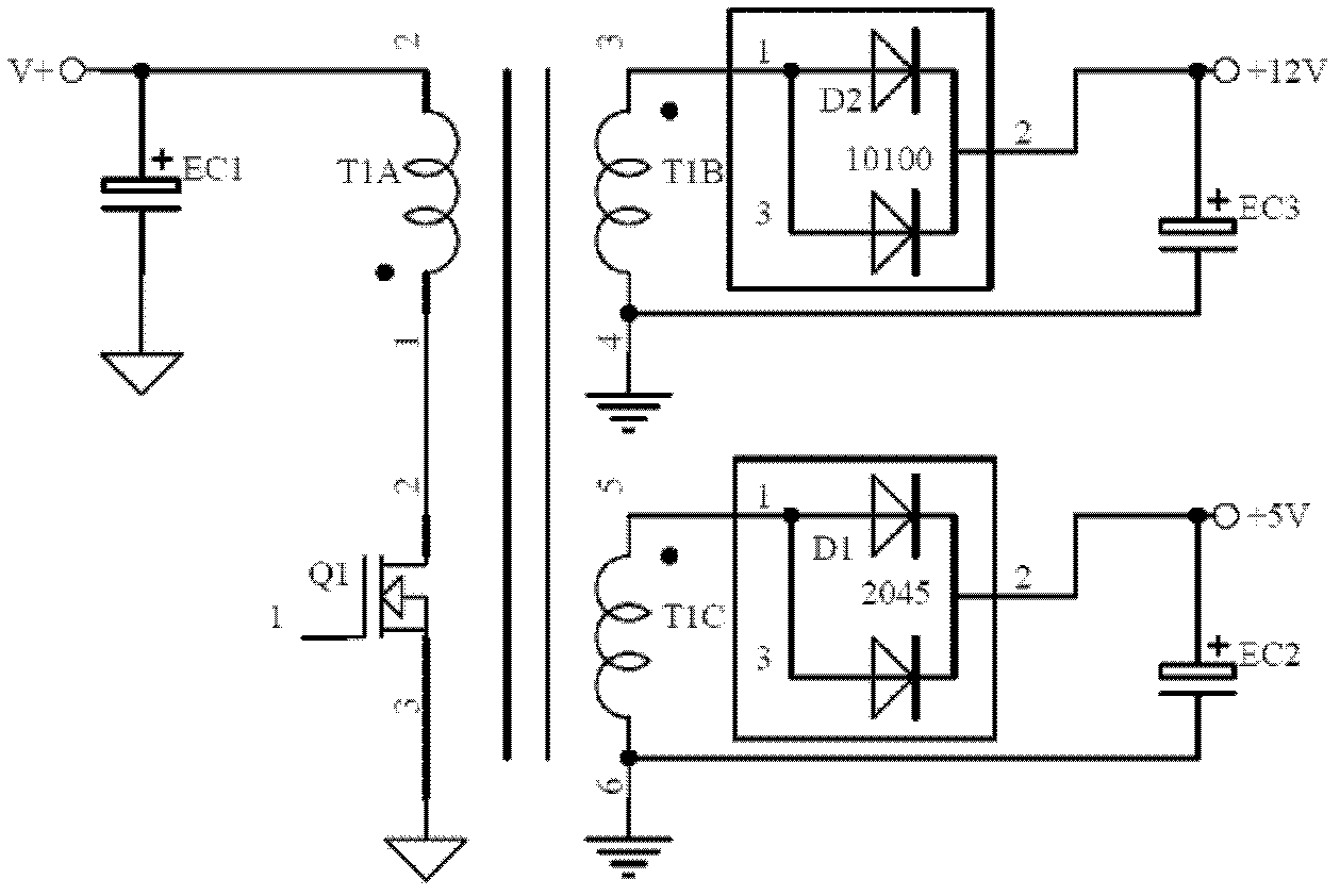
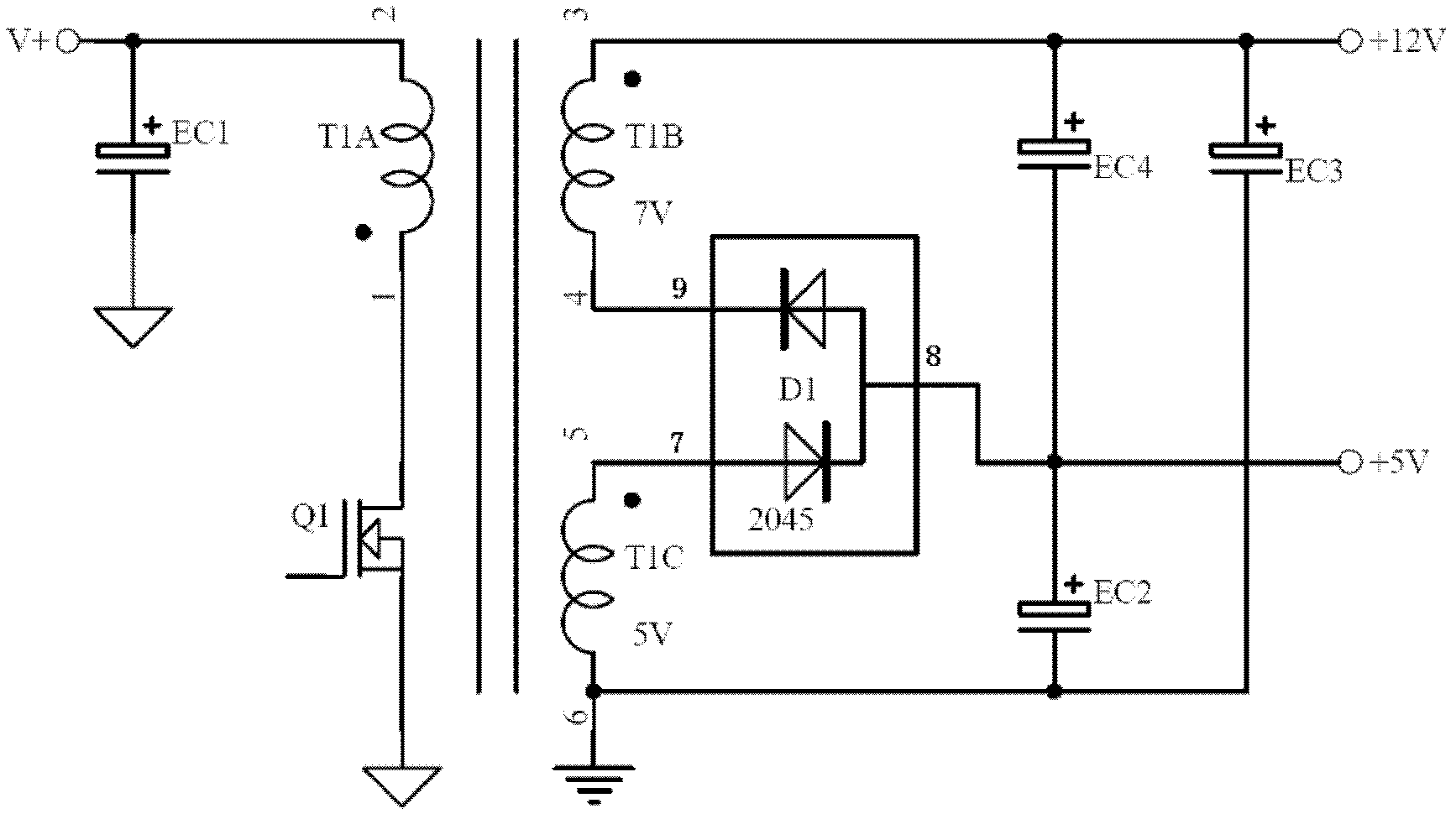
[0022] Example 1, figure 2 As shown, the present embodiment is a power supply circuit of electronic devices such as a TV set and a computer, and provides rectification circuits of switching power supplies of 5V and 12V power supplies for LCD, LED TV sets or computer motherboards, such as figure 2 As shown, it includes a first voltage output terminal that outputs 12V and a second voltage output terminal that outputs 5V. On the secondary coil of the transformer, 12V and 5V DC are formed through rectification.

[0023] The voltage stabilizing circuit of this embodiment is not different from that in the prior art, and the structure of the transformer is also the same. The in-phase end 1 of the primary coil T1A is connected to the drive tube, and the out-of-phase end 2 is connected to the first filter capacitor EC1, which has two secondary The coils are respectively the first secondary coil T1B and the second secondary coil T1C.

[0024] The 12V voltage output terminal is set at...


PUM


Abstract

The invention relates to a rectifier circuit, which comprises a Schottky diode and a filtering capacitor. A serial connection structure consisting of two diode wafers is packaged in the Schottky diode and provided with three pins including an anode of the Schottky diode, a cathode of the Schottky diode and a serial connection output pole of the two diode wafers. The rectifier circuit has the advantages that the rectifier circuit is low in cost, space-saving, beneficial to miniaturization, high in cross regulation rate, capable of reducing rectifier diode withstand voltage, and the like. Further, the problem of EMI (electromagnetic interference) is well solved.

Description

technical field [0001] The invention relates to the field of rectification circuits, in particular to a rectification circuit used in a switching power supply. Background technique [0002] At present, in industries such as LCD TV power supplies, motherboards generally use +5V, +12V for power supply. The current rectifier circuit of switching power supply such as figure 1 As shown, two Schottky diodes are usually required for rectification after the voltage regulator circuit. As shown in the figure, one D1 for +5, one D2 for +12V, and each Schottky diode package contains two diode chips to form a parallel connection. Schottky diodes, such as figure 1 As shown, there are two half-wave rectification circuits here, one is a half-wave rectification circuit for 12V power supply, and the other is a half-wave rectification circuit for 5V power supply. Among them, 5 power supplies use Schottky diodes of 20A45V Schottky 2045, and 12 power supplies use Schottky diodes of 10A100V Sc...

Claims


Application Information

Patent Timeline
Patent Type & Authority Applications(China)
IPC IPC(8): H02M7/10H02M1/12
Inventor 袁双全
Owner SHENZHEN MEGMEET ELECTRICAL CO LTD
Features
  • R&D
  • Intellectual Property
  • Life Sciences
  • Materials
  • Tech Scout
  • Unparalleled Data Quality
  • Higher Quality Content
  • 60% Fewer Hallucinations
Learn More