Hot nozzle core structure special for white pigment

A nozzle core and hot nozzle technology, which is applied in the field of hot runner hot nozzles, can solve problems such as wire drawing, salivation, and increased product defect rate, and achieve the effect of simple structure, balanced internal and external temperatures, and difficult wire drawing

Inactive Publication Date: 2012-08-22
SUZHOU HTS MOLD
View PDF0 Cites 2 Cited by
  • Summary
  • Abstract
  • Description
  • Claims
  • Application Information

AI Technical Summary

Problems solved by technology

[0005] The invention provides a hot nozzle core structure dedicated to white materials, and its purpose is mainly to solve the problem that the existing hot nozzle cores dedicated to white materials are prone to stringing and salivation when extruding color materials, resulting in increased product defect rates.

Method used


Image

  • Hot nozzle core structure special for white pigment
  • Hot nozzle core structure special for white pigment
  • Hot nozzle core structure special for white pigment

Examples


Embodiment

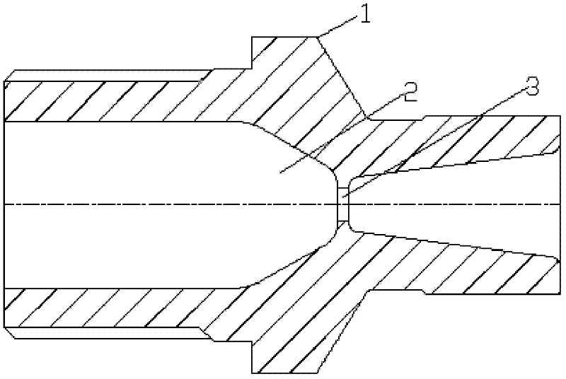
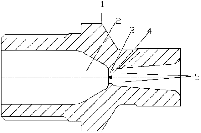
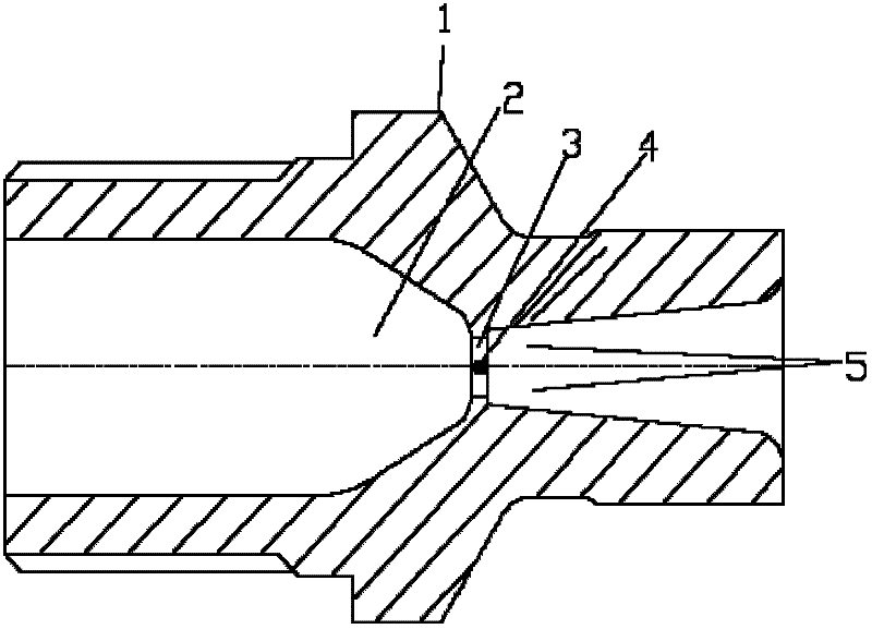
[0019] Such as figure 2 As shown, a hot nozzle core structure dedicated to white materials, including a nozzle core 1, a flow channel 2 that communicates with the nozzle body flow channel, and the end of the nozzle core 1 is used for the gate for the color material to flow out 3; The gate 3 is provided with a grid 4 laterally. The grid 4 divides the gate 3 into a plurality of spouts 5 .

[0020] The grid 4 is a knife-edge grid. The grid 4 is a frame made of a group of parallel grid bars, or a single grid bar. When the grid is a frame made of a group of parallel grid bars, the frame-type grid divides the gate 3 into several flow openings 5 ​​. When the grid is a grid bar, the grid bar divides the gate 3 into two shunt ports.

[0021] Since the present invention adds a knife-edge grid at the gate, the knife-edge grid can be a frame made of a group of parallel grid bars, or a single grid bar, so that a large material flow passes through the knife-edge grid At the gate, one ...


PUM


Abstract

The invention relates to a hot nozzle core structure special for a white pigment. The hot nozzle core structure comprises a nozzle core, a runner of the nozzle core and a pouring gate at an end part of the nozzle core, wherein the runner of the nozzle core is communicated with a runner of a hot nozzle body, and the pouring gate is used for discharging the pigment; and the pouring gate is provided with a grille, and the pouring gate is divided into a plurality of shunting ports by the grille. The scheme adopted by the invention is mainly used for solving the problem that the phenomena of wire drawing and drooling easily occur when the existing hot nozzle core special for the white pigment is used for extruding the pigment, and the qualified rate of products is increased.

Description

technical field [0001] The invention relates to a hot runner hot nozzle, in particular to a hot nozzle core structure of a hot runner system, especially a special hot nozzle core structure for white materials. Background technique [0002] At present, the injection mold commonly used in the injection molding industry is a hot runner injection mold, which generally includes a hot nozzle body, a flow channel inside the hot nozzle body, a nozzle core connected to the flow channel at the front end of the hot nozzle body, and a nozzle core located on the outer periphery of the hot nozzle body. The heating device is installed on the body of the hot nozzle to keep the injection plastic part in a molten state, flow through the flow channel and extrude from the nozzle body for injection molding. [0003] At present, different nozzle core structures are often used for different color materials, such as figure 1 As shown, it is a hot nozzle core structure dedicated to white materials,...

Claims


Application Information

Patent Timeline
Patent Type & Authority Applications(China)
IPC IPC(8): B29C45/27
Inventor 沈坚
Owner SUZHOU HTS MOLD
Why Eureka
Try Eureka