
Flexible material laser welding device

A flexible material and laser welding technology, which is applied in the field of flexible material laser welding devices to achieve the effects of high energy efficiency, reduced energy consumption and less human injury

Active Publication Date: 2014-08-20
SHANGHAI INST OF LASER TECH
View PDF5 Cites 0 Cited by
  • Summary
  • Abstract
  • Description
  • Claims
  • Application Information

AI Technical Summary

Problems solved by technology

[0003] The purpose of the present invention is to provide a laser welding device for flexible materials in order to overcome many shortcomings caused by the use of high-frequency heating and pressing rollers in the current welding of flexible materials.

Method used


Image

  • Flexible material laser welding device
  • Flexible material laser welding device
  • Flexible material laser welding device

Examples


Embodiment 1

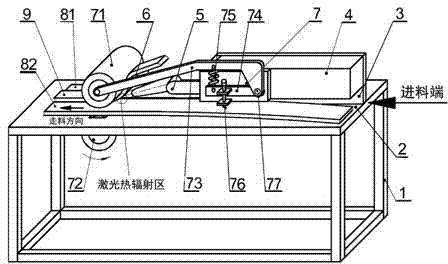
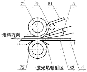
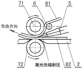
[0022] The material is a laminated composite material coated with hot melt adhesive on both sides. 2 The laser cuts and shapes the flexible material according to the drawings. Using CO 2 Laser and expand the beam spot. The laser power is controlled so that the spot after beam expansion is sufficient to melt the hot melt adhesive on the surface of the flexible material. Stack the edges of two pieces of flexible materials that are cut and shaped to be stitched together, clamped by the upper and lower pressure rollers, and form pressure on the two layers of flexible materials through the pressure arm, tension spring and tension adjustment arm. It is adjusted by the tension adjustment screw to obtain welding pressure between the materials to be welded. The laser irradiates the front area between the contact surfaces of the overlapped parts of the two layers of flexible materials to form a laser heat radiation area. The upper and lower pressure rollers are adjusted by their resp...

Embodiment 2

[0024]Using 808nm semiconductor fiber output laser, the material is a flexible PP polymer material doped with 808nm wavelength light-absorbing additives, the spot size is adjustable, and the laser power is controlled so that the set spot is sufficient to melt the surface and deep layer of the flexible material. Two pieces of flexible PP polymer materials of the same material are put together, covered with a strip-shaped auxiliary PP flexible polymer material, and its material can be different from the lower two pieces of flexible materials to be welded. The belt-shaped auxiliary PP flexible polymer material and the lower two flexible materials to be welded are clamped by the upper and lower pressing rollers, and the pressure is formed on the upper and lower layers of flexible materials through the pressing arm, tension spring and tension adjusting arm. The pressure is adjusted by the tension adjusting screw, so that welding pressure can be obtained between the upper and lower l...


PUM


Abstract

The invention discloses a flexible material laser welding device, which comprises a support vertical frame, a table-board, an installing vertical board, a laser, a light guide mouth, a material raising roller and a welding pressure head, wherein the table-board is fixed on the support vertical frame, a groove is arranged in the middle of the table-board, and the welding pressure head is arranged by striding the table-board; the installing vertical board is fixed on the middle line of the feeding end of the table-board; the welding pressure head is fixed on the table-board and the installing vertical board for clamping two to-be-welded flexible materials or two to-be-welded flexible materials where an auxiliary flexible material covers a tailored beam of the two to-be-welded flexible materials to be conveyed at constant speed; the laser and the material raising roller are fixed on the installing vertical plate, the material raising roller is used for raising the upper layer of the flexible material, the light guide mouth is connected with the laser, laser output from the light guide mouth irradiates the overlapping part of the two to-be-welded flexible materials or the overlapping part formed by covering the auxiliary flexible material on the tailored beam of the two to-be-welded flexible materials to form a laser heat radiation region, thus laser tailored welding and overlapping welding of the flexible materials are realized. The flexible material laser welding device has the advantages of good stability, environment friendliness, no strong electromagnetic radiation, little harm to a human body, low energy consumption and the like, and ensures consistent weld strengths and high welding efficiency.

Description

technical field [0001] The invention relates to a laser welding device for flexible materials. The welding device uses a laser to splice or laminate flexible material covering tapes, and belongs to the application field of laser processing technology. Background technique [0002] Usually flexible material welding is carried out by high-frequency heating and pressing rollers, but there are many disadvantages in using high-frequency hot ironing machines. 8 kW is also common. Therefore, when the high-frequency machine is working, the voltage of the local power grid is often lowered, which affects the safety of the surrounding power supply lines; when the high-frequency machine is working, it will generate a high-power electromagnetic wave with a frequency of tens of megabytes. The power of the high-frequency machine is too large, and it is difficult to filter the electromagnetic waves cleanly. The leakage of high-frequency interference through the power line can reach hundreds...

Claims


Application Information

Patent Timeline
Patent Type & Authority Patents(China)
IPC IPC(8): B29C65/16B29C65/78
CPCB29C66/83413B29C66/43B29C66/1142B29C66/1122B29C65/1658B29C65/4815B29C65/5092B29C65/1632B29C65/5042B29C66/71B29C66/8221B29C66/8227
Inventor 吴磊姜兆华陈俊张伟
Owner SHANGHAI INST OF LASER TECH
Learn More