Lobe separation equipment and method

A technology for separating equipment and slivers, applied in glass manufacturing equipment, optics, instruments, etc., can solve the problems of panel pollution, water residue on glass surface, difficult position control, etc., to achieve the effect of easy separation process

Active Publication Date: 2012-08-22
BOE TECH GRP CO LTD +1
View PDF5 Cites 10 Cited by
  • Summary
  • Abstract
  • Description
  • Claims
  • Application Information

AI Technical Summary

Problems solved by technology

Its disadvantages are: (1) Difficult to control the pressure: if the pressure is too high, it is easy to cause damage to the panel; if the pressure is too small, the glass waste will remain on the panel, which is difficult to remove; Difficult to grasp the position, near or far, easy to cause defects such as X-line (X-line) and chipping (Chipping) on ​​the obtained panel, and can not be used continuously
Its disadvantages are: (1) It is difficult to control the amount of water: when the amount of water doping is small, it is easy to cause insufficient splits; and when the amount of doping is large, it will cause water residue on the glass surface; (2) It is easy to cause panel pollution: in the water molecules Under the action of strong adhesion, the glass debris generated by scribing will be more likely to adhere to the glass surface, and it is difficult to remove

Method used


Image

  • Lobe separation equipment and method
  • Lobe separation equipment and method
  • Lobe separation equipment and method

Examples


Embodiment Construction

[0021] The split separation equipment and method proposed by the present invention are described in detail as follows in conjunction with the accompanying drawings and embodiments.

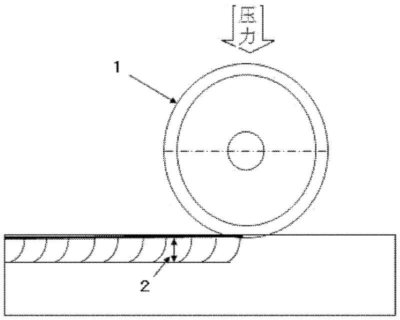
[0022] According to the principle of vibration, the equipment and method of the present invention make the cutting cracks on the glass substrate formed with cutting cracks fully extend in the thickness direction of the glass substrate, so as to achieve the effect of splitting the lobes.

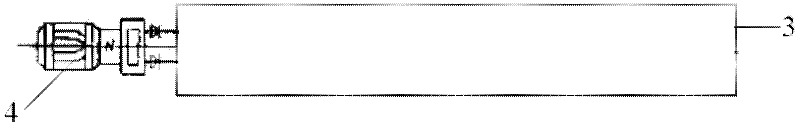
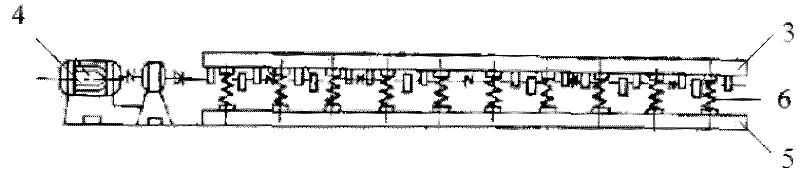
[0023] Such as figure 2 As shown, the splitting device according to an embodiment of the present invention includes: a vibration platform 3, which is used to fix at least one liquid crystal panel to be split, and drives the liquid crystal panel to vibrate, so that the cutting cracks on the glass substrate of the liquid crystal panel Fully extended during the vibration, the glass substrate fractures along the cutting crack, thereby achieving sliver separation.

[0024] The device in this embodiment further inclu...


PUM

PropertyMeasurementUnit
Resonant frequencyaaaaaaaaaa
thicknessaaaaaaaaaa

Abstract

The invention discloses lobe separation equipment and a lobe separation method and relates to the technical field of preparation of liquid crystal displays. The lobe separation equipment comprises a vibrating platform; and the vibrating platform is used for fixing at least one liquid crystal panel for lobe separation and drives the liquid crystal panel to vibrate, so that a glass substrate of the liquid crystal panel is cracked along a cutting crack. The equipment and the method have the beneficial effects that according to a vibration principle, the cutting crack on the glass substrate for forming the cutting crack fully extends along the thickness direction of the glass substrate to achieve the lobe separation efficiency, the separation process is easy to control, and no pollution and no damage can be caused to the liquid crystal panel.

Description

technical field [0001] The invention relates to the technical field of liquid crystal display preparation, in particular to a split separation device and method. Background technique [0002] In the liquid crystal display (LCD) manufacturing process, after the array substrate and the color filter substrate are boxed together, a large liquid crystal panel is generally formed first, and the entire liquid crystal panel needs to be cut and scribed to obtain a liquid crystal panel of the required size. Such as figure 1 As shown, the diamond guide wheel 1 is used to cut and roll the liquid crystal panel. Under pressure, the glass forms cutting cracks 2 perpendicular to the glass surface on the cutting line. The depth of the cutting cracks 2 is about 80-110 μm. The thickness of the glass substrate used in the liquid crystal panel is generally 0.5mm to 1.1mm. After cutting, the entire liquid crystal panel with cutting cracks needs to be transported to the split separation platform ...

Claims


Application Information

Patent Timeline
Patent Type & Authority Applications(China)
IPC IPC(8): C03B33/033
CPCC03B33/033G02F1/133351B65G2249/04G02F1/1333
Inventor 刘晓旺郭宏雁刘汝涛龚中波朱家志
Owner BOE TECH GRP CO LTD
Why Eureka
Try Eureka